Fusion 360 Fully Constrained Sketches
Updated: 2026-05*
This article was written before 2020. It is kept here as an archive — the content is outdated and some links may no longer work.
What Is Full Restraint?
“Fully constrained” refers to a state in which a shape is fixed by specifying all the dimensions and constraints required for the design when creating a drawing. Fully constrained shapes appear in black.
By specifying dimensions and constraints that accurately reflect the design intent, it becomes easy to accommodate specification changes and create variations.
Creating a Flat-Cornered Rectangle
In this exercise, we will make a flat corner bracket, a type of joinery hardware used in woodworking.
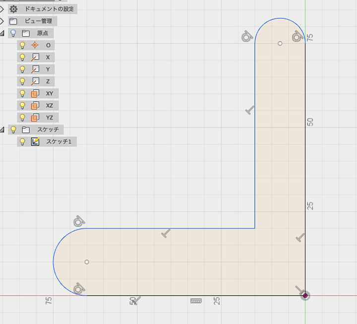
Drawing the Outline
Use the Line Segment and Arc tools to draw the outline.
Align the bottom-right corner with the origin. The dimensions at this stage are just a rough guide.
Draw the figure so that horizontal and vertical constraints are automatically applied.
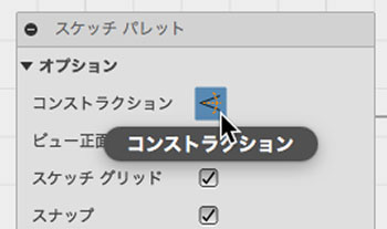
Construction Drawing
While in line segment construction mode, enable the “Construction” option in the Sketch palette.
Construction lines are not merely auxiliary lines; because they are affected by dimensions and constraints, they can be used to build the structure of a shape. However, they do not affect the division of face areas.
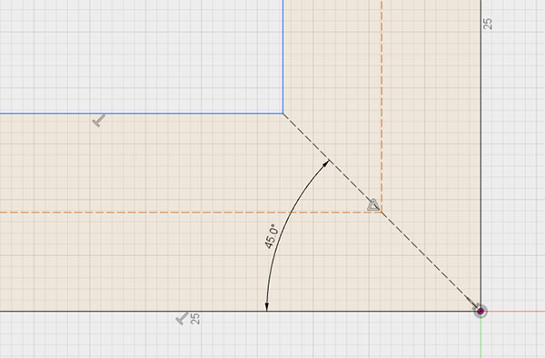
Draw the construction as shown in the figure below.
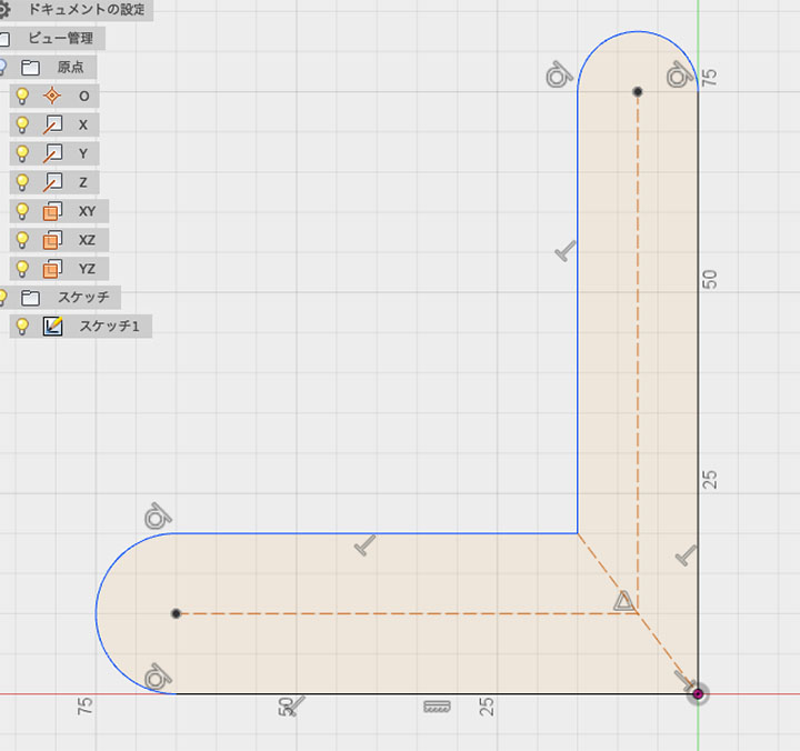
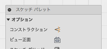
After drawing, make sure to turn off the construction tools in the Sketch palette.
Setting the Angle
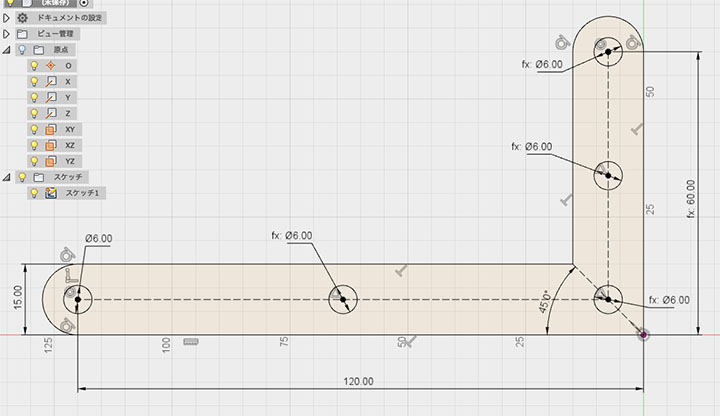
As shown in the figure below, specify a 45-degree dimension on the construction line drawn diagonally at the right angle.
If the outline is drawn horizontally and vertically, this constraint alone ensures that the widths in the horizontal and vertical directions are the same.
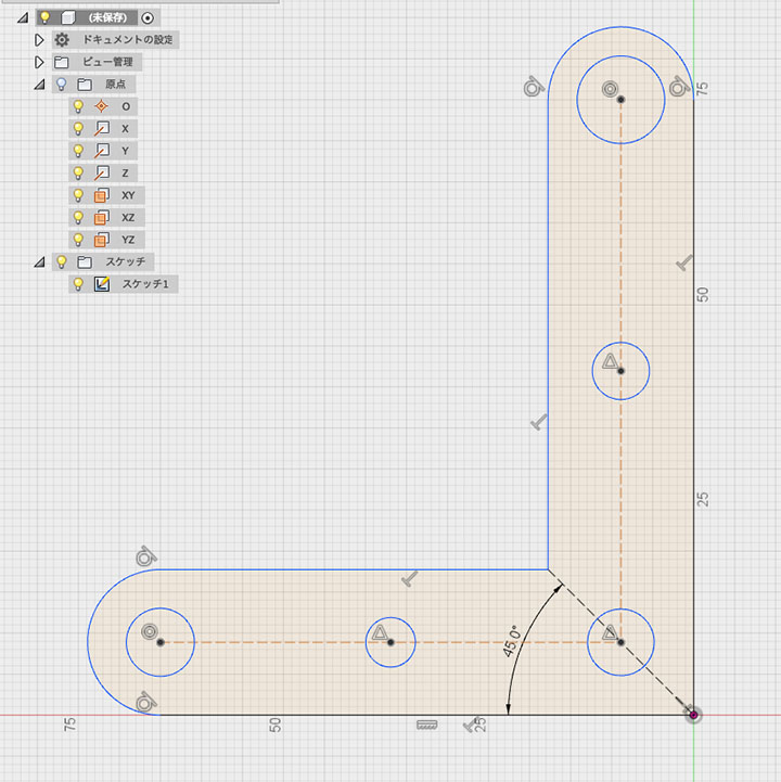
Constructing a Circle
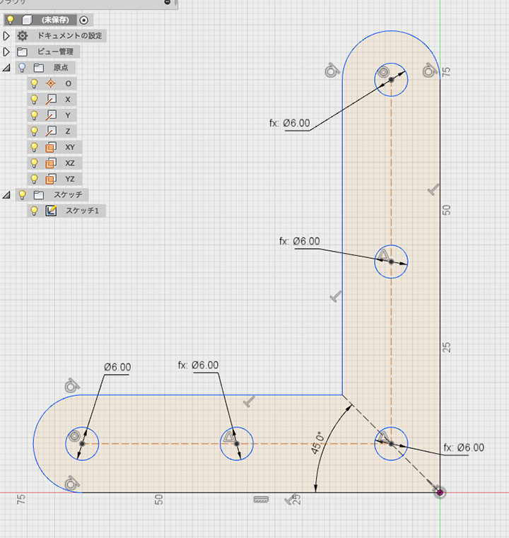
Create five circles (specifying the center and diameter) as shown in the figure below. The diameter can be approximate.
Draw the circle at the midpoint of the construction at the position where the triangle midpoint constraint icon appears.
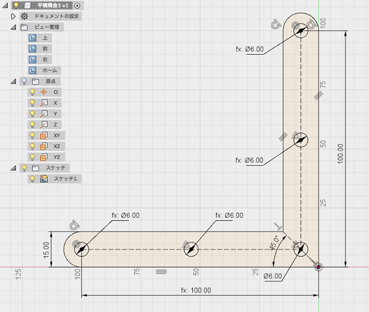
Specifying the Diameter
Specify a diameter of 6 mm for the circle in the lower left.
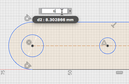
When specifying the diameter of the second circle from the left, you can create a parameter link by clicking the diameter dimension of the first circle.
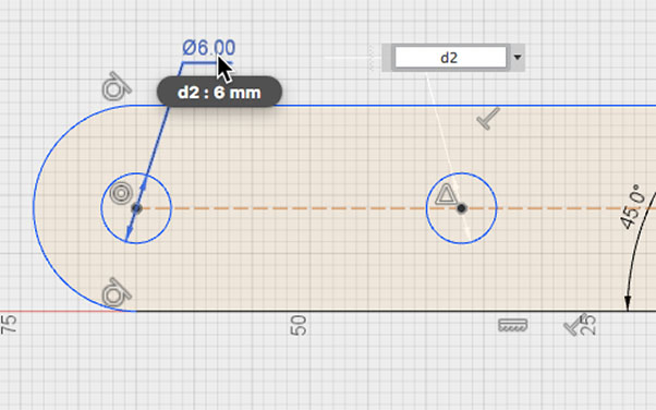
Similarly, link the diameters of all circles to the diameter of the bottom-left circle.
Using this method, changing the diameter of a single circle will automatically update the diameters of all circles.
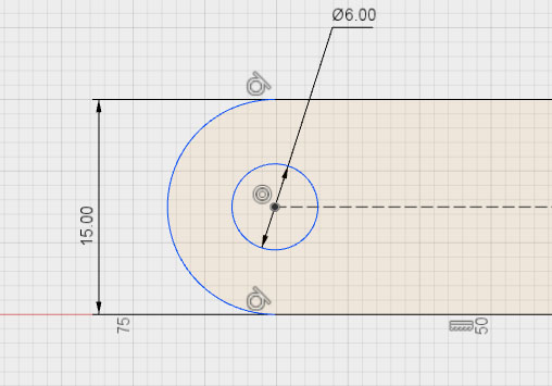
Specifying Width
As shown in the figure below, specify a horizontal width of 15 mm.
Due to the 45-degree constraint on the diagonal construction at the right angle, the vertical width is automatically set to 15 mm.
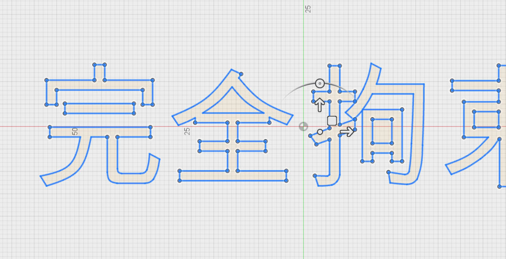
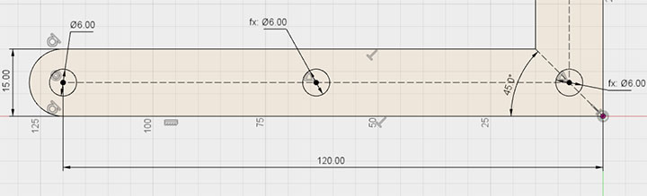
Specifying Length
Set the horizontal length to 120 mm.
For shapes that are fully constrained, the line color changes from blue to black. For shapes with multiple parameters, such as circles, the line color turns black when both the position and diameter are constrained.
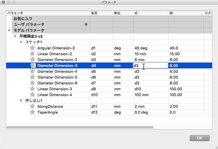
To calculate the vertical length, link the horizontal length as a parameter, then enter the formula (parameter name/2) as shown in the figure below.
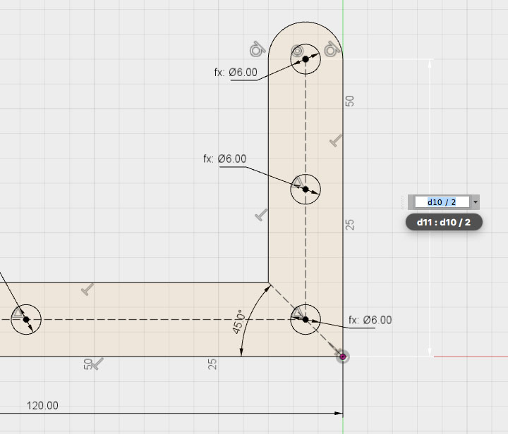
With this method, simply changing the horizontal length automatically calculates the vertical length as half of that value.
*Due to a bug in Fusion 360, parameter links on the outer side of rounded arcs do not function correctly.
Extrusion and Chamfering
Stop sketching.
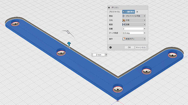
Set the distance (thickness) to 2 mm for the extrusion.
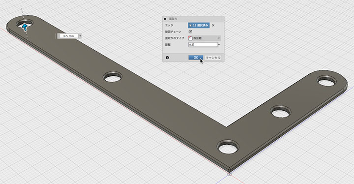
Set the edge rounding to 0.5 mm, as shown in the figure below.
Re-editing a Sketch
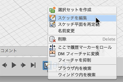
You can easily change the specifications by clicking “Edit Sketch” from your history or browser.
Checking and Changing Parameters
Edit > Change Parameters: From here, you can view and modify parameter names and values.
You can change not only the dimensions but also the parameters of extrusion and chamfer features all at once.
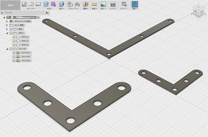
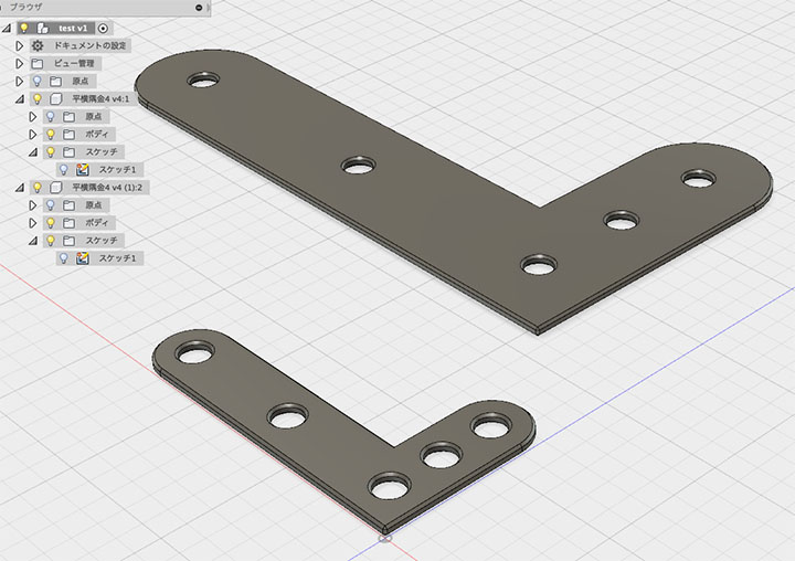
Creating Variations
After creating a new design, load the existing design as a component and unlink it.
After duplicating them, you can create variations with different specifications by editing each sketch.
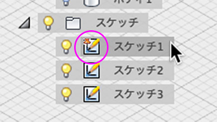
The Sketch icon in the browser
When you fully constrain a sketch, a pin icon appears on the sketch icon in the browser.