Fusion 360 Basics
Updated: 2026-05*

This article was written before 2020. It is kept here as an archive — the content is outdated and some links may no longer work.
What is Fusion 360?
Fusion 360 Official Website
http://www.autodesk.co.jp/products/fusion-360/
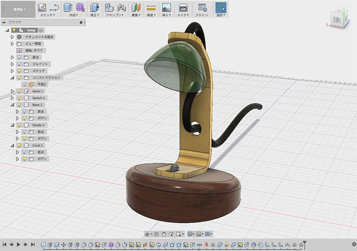
Fusion 360 is a 3D CAD tool developed by Autodesk. It includes not only CAD capabilities but also CAM, simulation, assembly, rendering, and animation features, making it an all-in-one, next-generation digital fabrication tool with cloud capabilities.
In addition to desktop applications that run on Mac and Windows, a browser version (WIP) and a mobile app data viewer are also available.
Highly Flexible Workflow
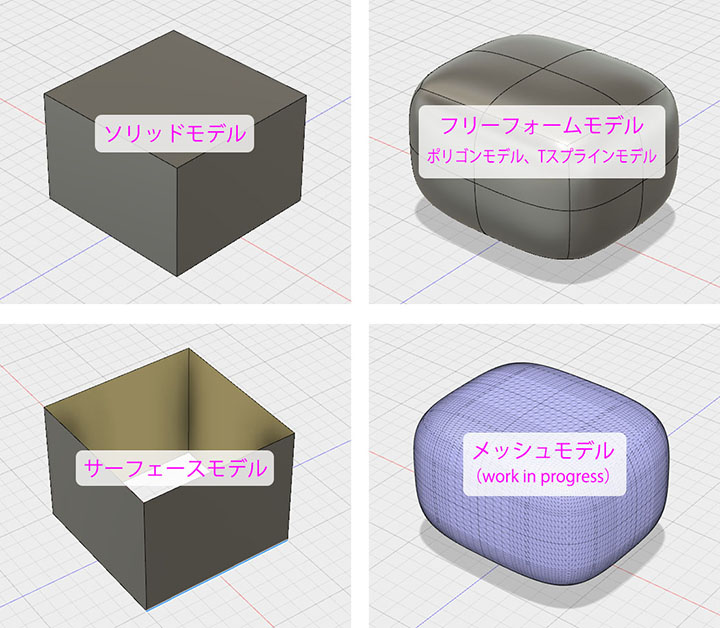
Fusion 360 supports solid models, surface models, free-form models, and mesh models (WIP), and allows you to convert between these formats. This highly flexible modeling environment enables you to select the optimal modeling method for creating your desired 3D shape, design an efficient workflow, and focus on your creative work.
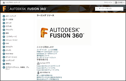
Useful Information Sites
Online
Help: Official Japanese online help.
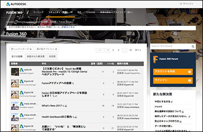
Experts answer a wide range of questions from community site
users.
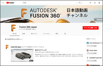
Features numerous tutorials from the official Fusion 360 YouTube channel
.
Online Seminars
: You can view seminar videos and materials here.

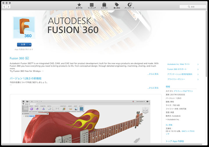
Installation (Configuration Complete)
For the Mac version, download and install it from the App Store.
Account Creation (Already Set Up)
To use Fusion 360, create an Autodesk account.
An Autodesk account can be used not only for Fusion 360 but for all Autodesk services.
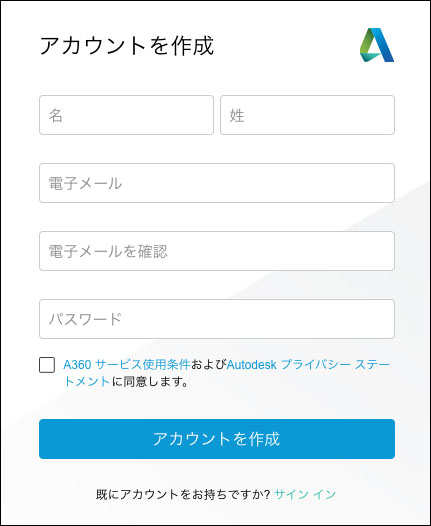
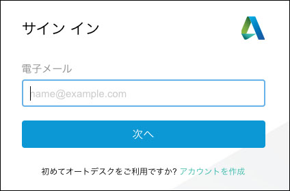
Launch Fusion 360 and click “Create Account” in the lower-right corner of the sign-in screen.
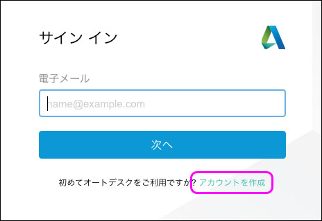
Enter the required information, including your email address, to create an account.
You will receive a confirmation email. Click the link in the email to open the website and complete the confirmation.
Sign up as a student or educational institution (already set up)
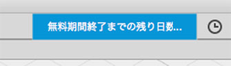
After signing in to Fusion 360 with your email address and password, click the icon shown below in the upper-right corner of the application bar.
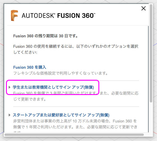
A window like the one shown below will appear in the center; click “Sign up as a student or educational institution.”
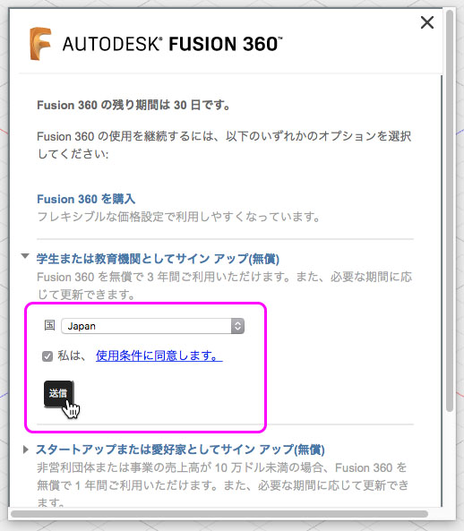
Agree to the terms of use and submit as shown below.
Sign In
After launching Fusion 360, enter your email address on the sign-in screen.
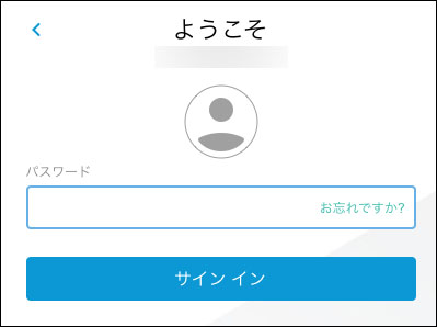
Enter your password to sign in.
Data Panel
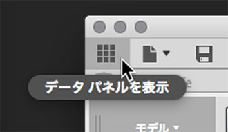
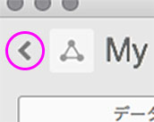
Click the icon in the lower-left corner of the figure below to display the data panel.
“My First Project” appears on the left side of the window.
Saved and uploaded data is managed in this cloud storage space.
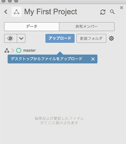
Click the arrow in the lower-left corner of the figure below to go up a level.
Here, you can create a new project or use sample data.
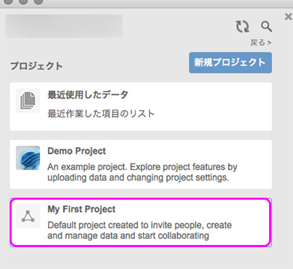
To return to “My First Project,” double-click “My First Project” in the image above.
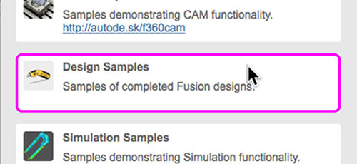
Open Sample Data
Double-click “Design Samples” in the Data Panel.
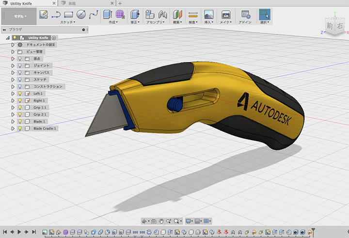
Right-click on “Utility Knife” to open it.
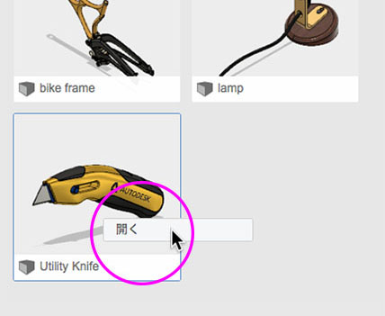
The Sample Designs tab opens.
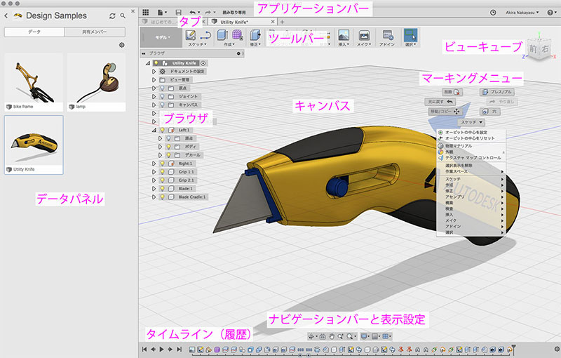
User Interface
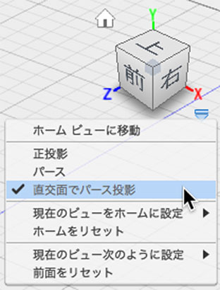
ViewCube
You can move the camera using ViewCube.
You can go to the Home view by tapping the Home icon in the upper-left corner.
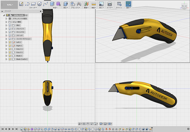
In this exercise, select “Orthogonal Perspective” from the options in the lower-right corner.
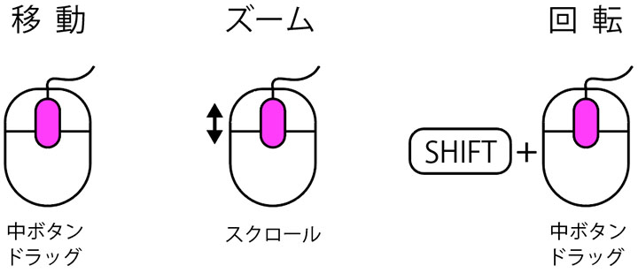
View Manipulation Using the Mouse
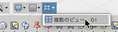
Multiple Views
You can switch between multiple views from the Viewport menu.
This exercise is generally conducted using a single view.
Browser
In Fusion 360, the design process involves a series of complex steps, which can be confusing.
You’ll use the browser to manage and work with a large number of sketches and bodies.
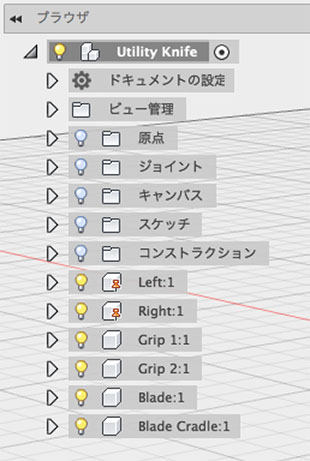
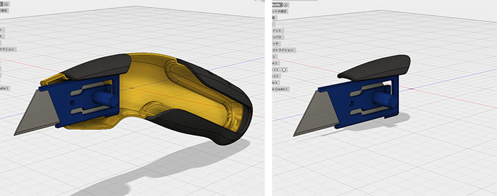
Try clicking the lightbulb icons for the Utility Knife components—Left, Right, Grip1, Grip2, Blade, and Blade Cradle—to show or hide them.
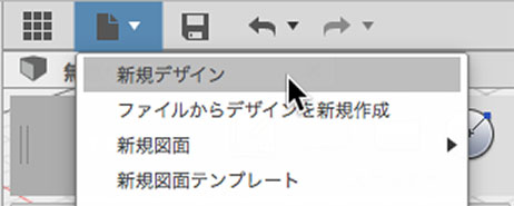
Creating a New Design
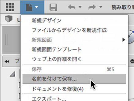
Create a new design from the File menu.
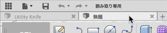
In Fusion 360, you can open multiple designs at the same time.
Tabs will appear as shown below; click to switch between them.
To close the design, click the “X” on the right side of the tab.
Save Design / Save As
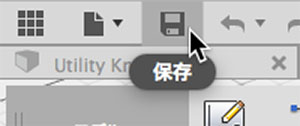
Save
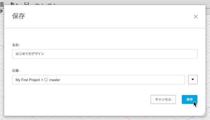
To save your design, click the floppy disk icon on the application bar.
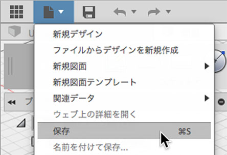
You can also save by selecting “Save” from the File menu or pressing Command+S.
Here, enter “My First Design” as the name and save it.
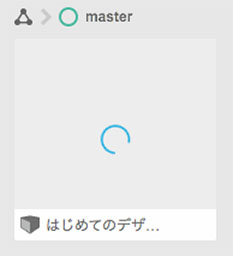
The data is saved to the data panel (in the cloud). An animation like the one shown below will appear; please wait until the upload is complete.
To save as a different file with a new name
Toolbar
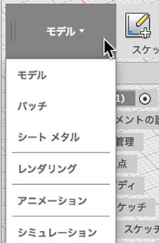
Fusion 360 offers the following modes, allowing you to switch between workspaces to access different features.
・Model
・Sculpt
・Patch
・Sheet metal
・Rendering
・Animation
・Simulation
・CAM
・Drawings
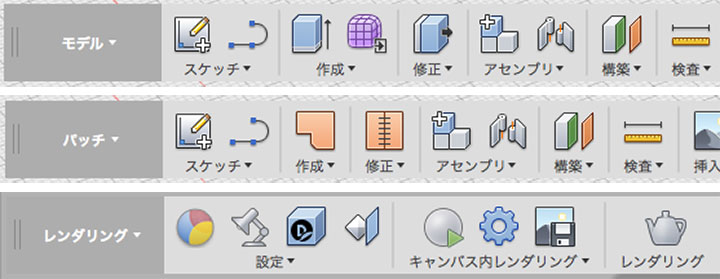
You can switch between modes (workspaces) by clicking on their names.
To enter Sculpt Mode, click the “Create Form” button on the Model Mode toolbar.
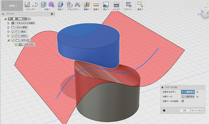
Model Mode = Solid Modeling
Because Model Mode is designed for solid modeling with volume, cross-sections are automatically generated when you cut through the model.
In this class, we will begin by explaining solid modeling.
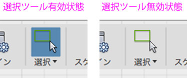
Selection Tools
You can select bodies, faces, or sketches when the selection tool is active (as shown on the left in the figure below).
When drawing shapes or applying constraints, the selection tool remains active (as shown on the right in the figure below), and you cannot perform other tasks while in this state. To exit this state, click the selection tool or press the ESC key.
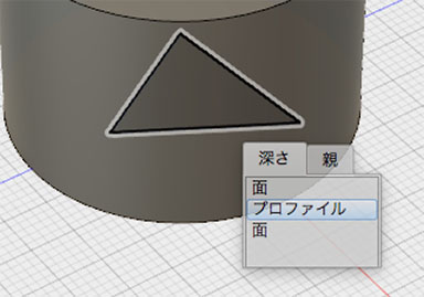
If you can’t select an item in the background, press and hold to select it from the depth.
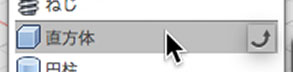
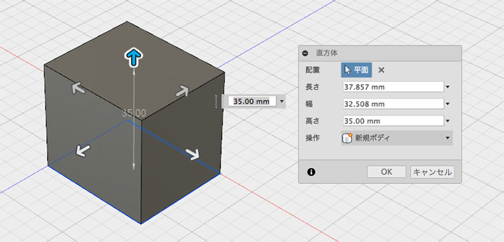
Creating Primitive Objects
Rectangular Prism
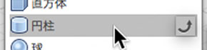
Cylinder

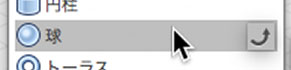
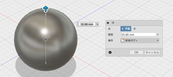
Ball
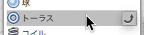
Torus
Deleting Objects
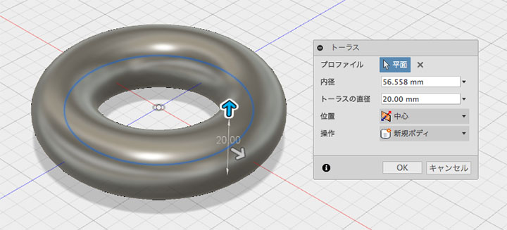
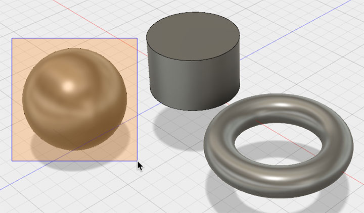
Here, we will delete everything except the cuboid.
Select one of the objects (bodies) by drawing a selection box around it, then press the Delete key. The object must be completely enclosed within the selection box.
When selecting regions, multiple bodies with faces cannot be selected simultaneously (spheres and tori can be selected).
Since you can select multiple items in the browser’s body, you can delete them all at once.
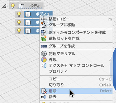
Moving/Rotating and Copying Objects
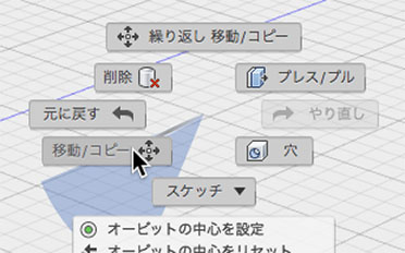
Moving from a blank state
Right-click on an empty area of the workspace and select “Move/Copy” from the context menu.
Select a face or vertex of the cuboid. The direction of the pivot axis changes depending on the selected position.
Verify that the area marked in the dialog box below is the body.
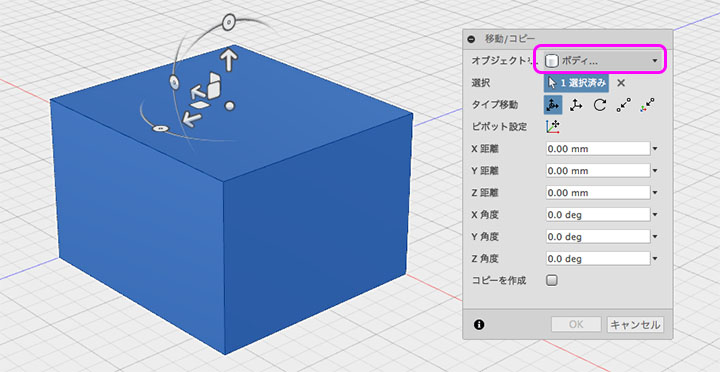
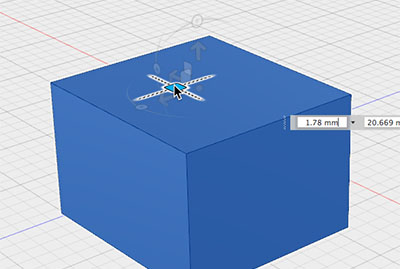
There are four ways to use the helper.
Axis-Constrained Movement
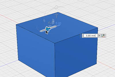
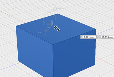
Moving Plane Constraints
Free Movement
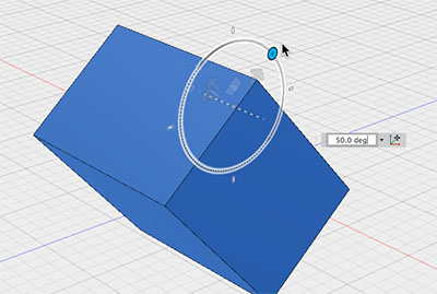
Rotation with Axis Constraints
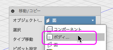
Moving from a Selected State
Right-clicking on a body’s vertices or edges works the same as described above, but right-clicking on a face will move or rotate the face.
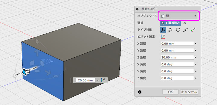
To move a body, select “Body” from the drop-down menu shown below.
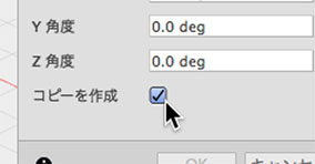
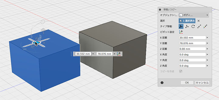
Copy
To copy, check the “Create a copy” box in the dialog box before moving the item.
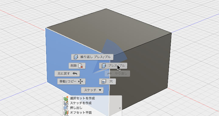
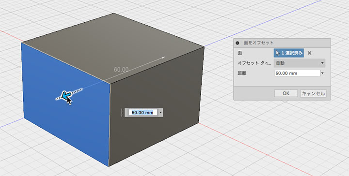
Face Press/Pull
Right-click on the surface and select “Push/Pull” from the Marking Menu.
It is similar to moving a face, but you cannot rotate it using the press/pull command.
Note that pressing or pulling vertices or edges creates a fillet.
You can drag the helper to offset the face.
Grid Snapping
By default, grid snapping is enabled for mouse operations such as moving the body.
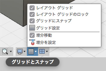
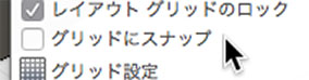
Unchecking the “Snap to Grid” option allows for more precise adjustments.
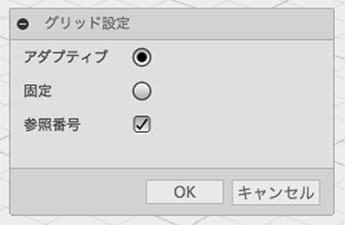
By default, the grid is set to “Adaptive,” which means the grid size changes depending on the zoom level and is not fixed. If you want a fixed grid size, select “Fixed” and set the grid value.
Undo/Redo
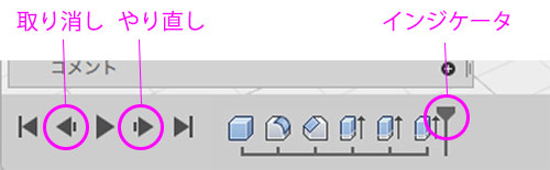
Application Bar
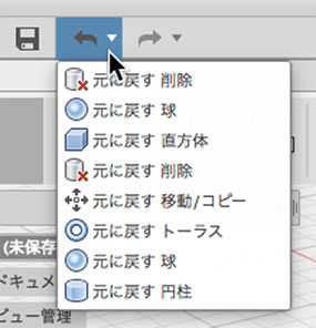
You can use the buttons on the application bar to undo or redo actions.
▼You can also select an item from the history by tapping this area.
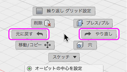
From the Marking Menu
Keyboard Shortcuts
Undo: Command+Z
Undo: Command+Shift+Z
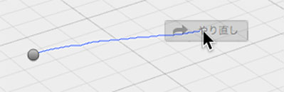
Right-click and drag gesture
Drag to the left while holding down the right mouse button, then release the button to undo.
Drag to the right, then release the button to redo.
However, depending on how you use it, it can trigger other functions, so I don’t recommend it unless you’re an expert.
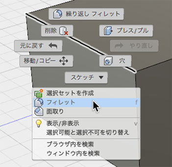
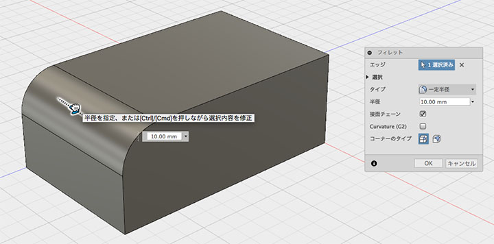
Fillet (Rounded Corners)
Right-click the edge and select “Fillet” from the Marking Menu.
Apply a fillet by using a helper or specifying a value.
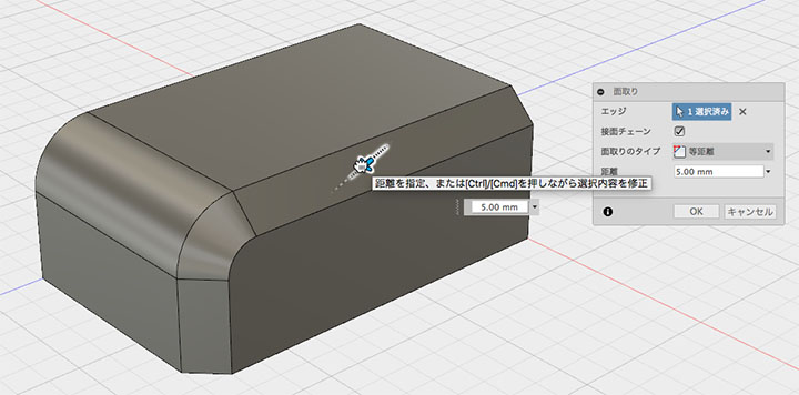
Chamfering
Right-click the edge and select “Chamfer” from the marking menu.
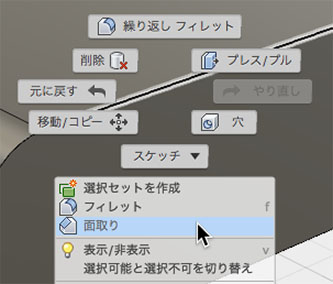
Apply a chamfer by using the helper tool or specifying values.
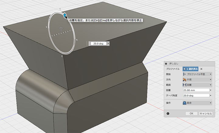
Extrusion
Right-click the face and select “Extrude” from the Marking Menu.
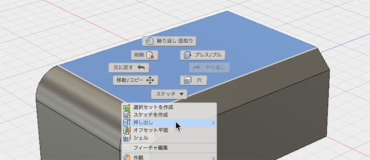
Apply a chamfer by using the helper tool or specifying values.

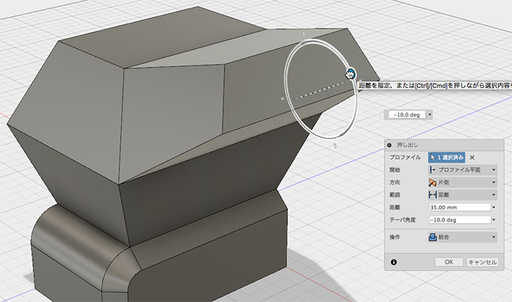
It is also possible to apply a taper at the same time as the extrusion.
Add extrusions and chamfers.
Timeline
You can navigate the timeline to go back to past entries.
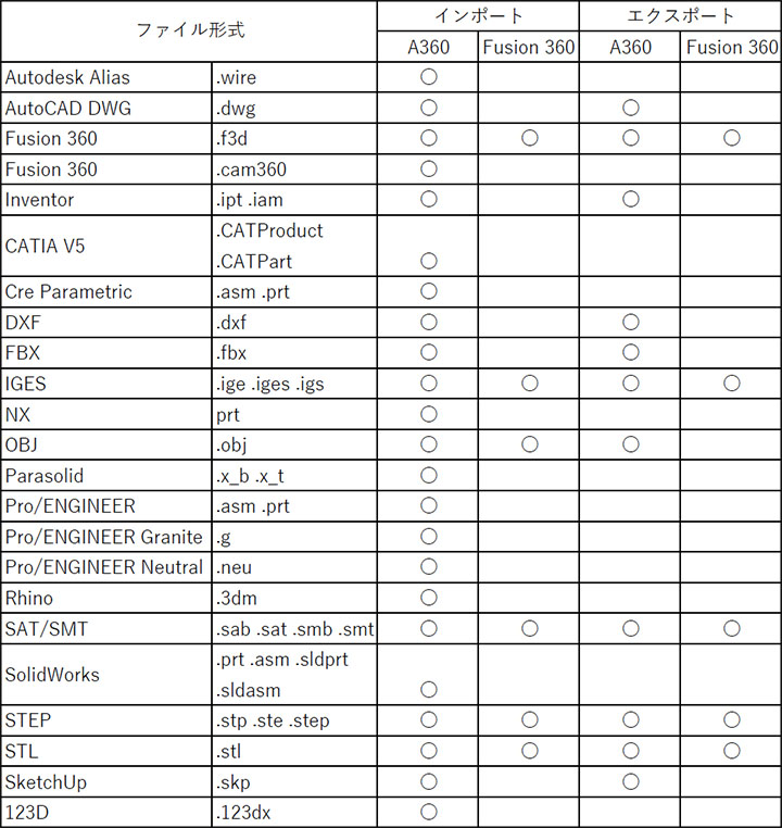
Input and Output Formats
The file formats supported for import and export in the desktop application (Fusion 360) differ from those supported for import and export via data conversion in the cloud (A360).
As shown in the table below, it is possible to handle various data formats in conjunction with cloud functionality.
Saving .f3d Files to the Desktop
Assignments for this exercise must be submitted in the .f3d format, which is the Fusion 360 archive file format.
Saving to the Desktop
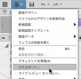
Click File Menu > Export.
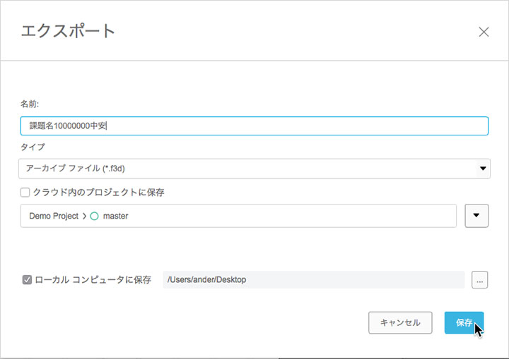
Change the name. The name will be specified for each assignment.
Change the file type to “Archive File (*.f3d)”.
Check the box to save to the local computer.
Change the save location to the desktop.
Click the Save button. Instructions on where to submit your work will be provided during class.
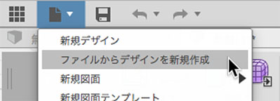
Open Desktop Data
Click File > New Design from the File menu.
Select a file on your desktop and open it.
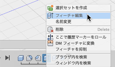
Feature Editing
You can edit past features by right-clicking the history icon.
This feature allows you to experiment with different parameter settings.
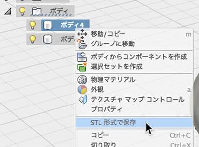
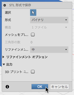
Saving in STL Format
STL files are saved via the browser’s body.
Saving Data and Closing the Application
Since CAD applications put a strain on your computer, be sure to save your data frequently.
Since the data is saved to the cloud, it takes a little longer than saving it locally.
Wait until the data panel’s upload animation finishes.
Save the data before exiting the application.