Arduino Basics
Updated: 2026-05
This article was written before 2020. It is kept here as an archive — the content is outdated and some links may no longer work.
Parts List
List of Parts Distributed at Kobe Design University
- 1 Arduino UNO + breadboard
- 1 USB cable
- Battery cable (9V DC battery snap + 2.1mm DC plug, center positive)
- 6 red jumper wires *Since the exact number of wires needed is unknown, we will provide more if you run out during the activity.
- 6 black jumper wires
- 3 green jumper wires
- 3 white jumper wires
- 1 blue jumper wire
- 1 tact switch (2-pin)
- 1 3-axis accelerometer (KXR94-2050 or KXM52-1050)
- CDS (light sensor): 1
- LED (light-emitting diode): 1
- ECM (electret condenser microphone) unit: 1
- 10kΩ resistor (brown-black-orange-gold): 2
- 470Ω resistor (yellow-purple-brown-gold): 1
Once all processes are complete, place the cables in the large bag and the electronic components in the small bag for return.

What is Arduino?
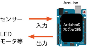
From the perspective of electronic circuits, an Arduino can be considered a superset that includes a microcontroller, a power supply, and peripheral circuits; however, when viewed from the perspective of its role, it can be described as an intermediary between a computer and the real world, or an input/output (I/O) interface that converts analog values to digital values.
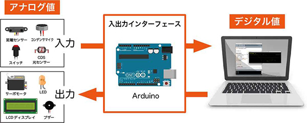
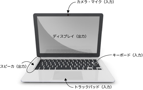
PCs already come equipped with input and output devices such as webcams (input), microphones (input), speakers (output), keyboards (input), mice (input), and displays (output). You can think of Arduino as a kit that allows you to create your own custom input and output devices using sensors and actuators.
Systems Using Arduino
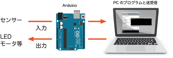
A System That Functions as an Interface
A system that serves as an interface for a PC by linking with PC programs.
Standalone System
A standalone system that uses a PC only for programming; once programmed, it operates independently using only the Arduino.
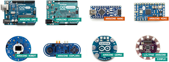
Different Types of Arduino
There are many different types of Arduino boards (see the official PRODUCT page). With a wide variety of shapes and features available, you can choose the one that best suits your project. The Arduino UNO, which we’ll be using here, is ideal for beginners or as a general-purpose board.
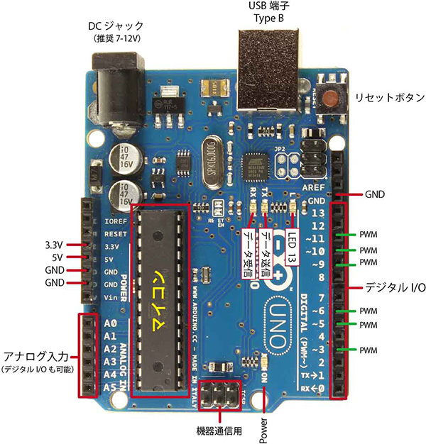
Arduino UNO R3 Pin Layout
The pin layout and board configuration of the Arduino UNO R3 are shown in the figure below. Power is typically supplied via USB, but you can also connect an AC adapter to the DC jack or run it on batteries.
*Note: While there are different versions of the Arduino UNO depending on when it was sold, the one used here is the R3.
The information provided here covers only some of the Arduino UNO’s features; since not all information is included, you should carefully review the specifications before use.
・Arduino UNO & Genuino; UNO Product Page (English)
Understanding Circuit Diagrams
To understand electronic circuits, you need to interpret circuit diagrams with an understanding of the characteristics of electronic components.
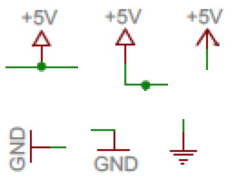
The figure below shows a portion of the Arduino UNO circuit diagram.
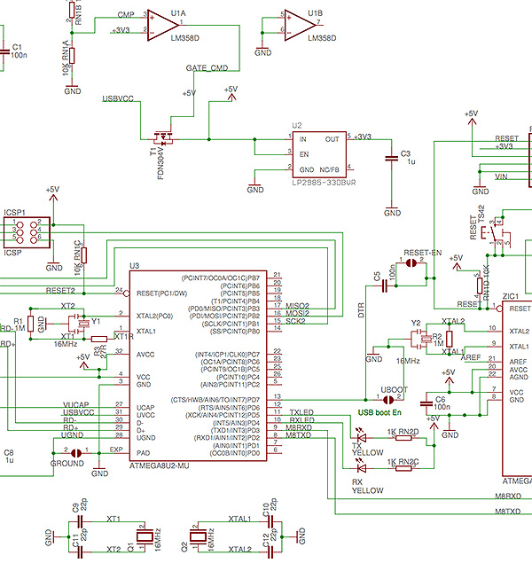
I won’t explain everything here, but I will focus on the power supply section. As shown in the figure below, there are multiple symbols for +5V and GND; this means that the +5V lines are connected to each other, and the GND lines are connected to each other. In the circuit diagram, these connections are omitted to simplify the drawing.There aren’t actually multiple +5V power supplies. However, you need to be careful because a single circuit may have multiple power supplies. Even the Arduino UNO has two power supplies: +5V and +3.3V. GND is shared.
Setting Up Arduino
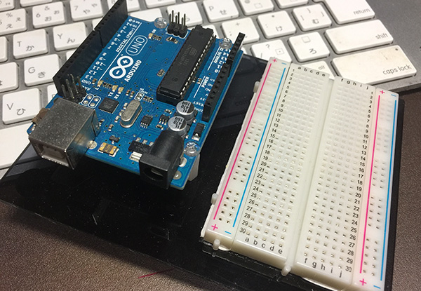
Arduino UNO R3 + Breadboard EIC-80
This setup uses an Arduino UNO R3 and a breadboard mounted on an acrylic base.
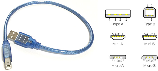
USB Cable (Type A – Type B)
The Arduino UNO uses a Type A to Type B USB cable.
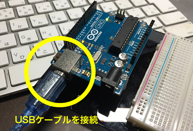
Connecting the Arduino
Connect the Arduino to the PC using a USB cable.
Launching the Arduino IDE
Launch Arduino184.app from the Applications folder.
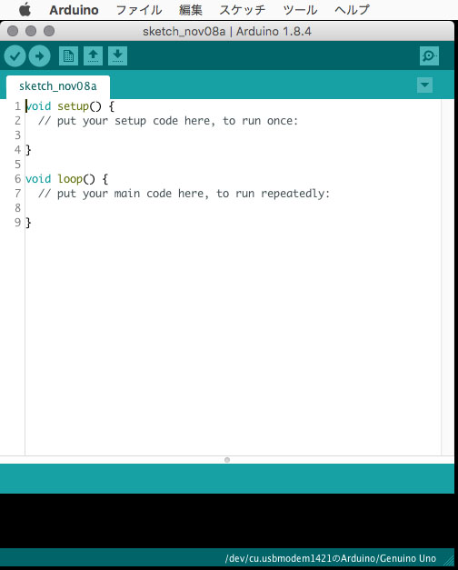
A basic sketch appears.
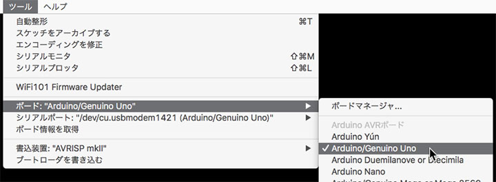
Choosing a Board
Tools Menu > Board > Arduino/Genuino Uno
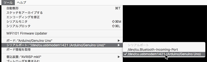
Selecting a Serial Port
Tools Menu > Serial Port > /dev/cu/usbmodem***** (the numbers vary depending on your environment)
Blinking LED
1. Sample Sketch
Open File Menu > Sample Sketches > 01.Basics > Blink.
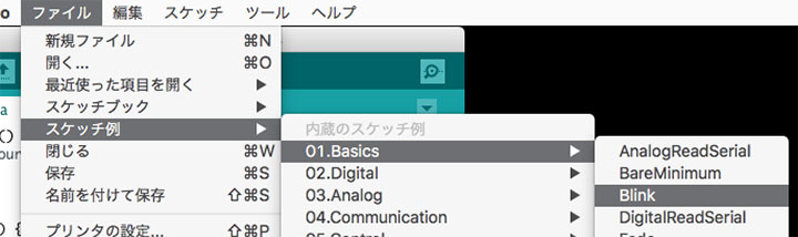
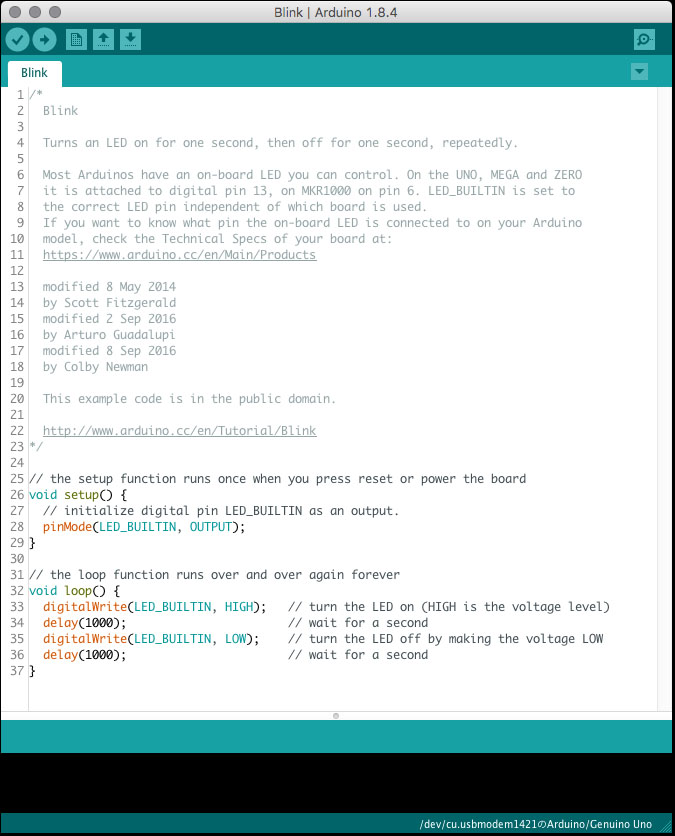
The sample sketch (Blink) appears.
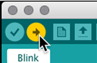
2. Compile
Click the Verify (Compile) button.

The status bar displays “Compiling sketch” or “Compilation complete.”


3. Post
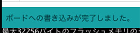
Click the “Post” button.
The status bar displays “Writing to the microcontroller board” and “Writing to the board complete.”

4. Checking LED Operation
Verify that the LED (L) on the Arduino is blinking.
⑤ Understanding the Sketch
// The setup function runs once when you press the reset button or power up the board
void setup() {
  // Initialize digital pin LED_BUILTIN as an output.
  pinMode(LED_BUILTIN, OUTPUT); // Set the pin as an output. For the UNO, LED_BUILTIN (reserved variable) = 13
}

// The loop function runs continuously indefinitely
void loop() {
  digitalWrite(LED_BUILTIN, HIGH);   // Turn the LED on (HIGH is the voltage level)
  delay(1000);                       // wait for a second (1000 ms)
  digitalWrite(LED_BUILTIN, LOW);    // turn the LED off by setting the voltage to LOW
  delay(1000);                       // wait for a second
}