Live-Action VFX - Part 1
Updated: 2026-05
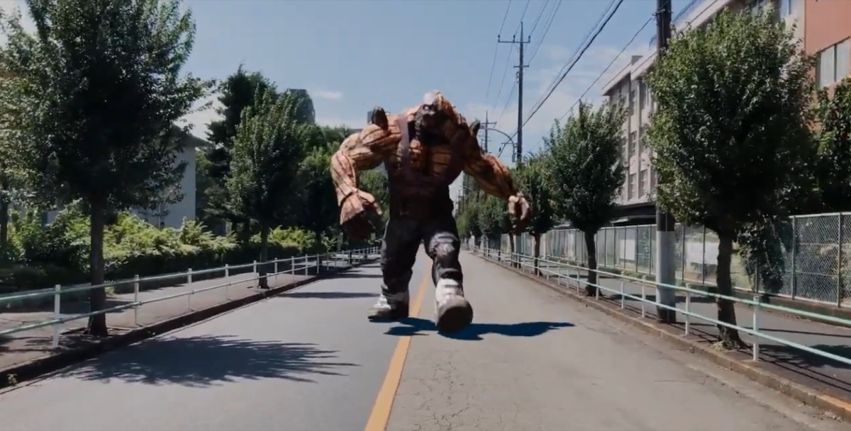
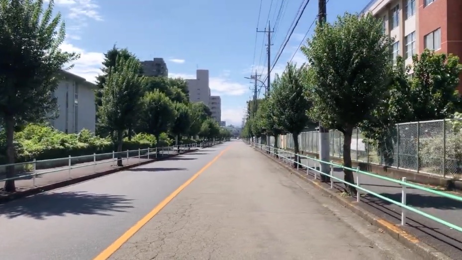
1. Goal - Hino Kaiju A
In this exercise, we will create a composite of a Mixamo character walking along the road north of the Hino Campus of Tokyo Metropolitan University. The video below was rendered in Eevee without an HDRI, using two Sun Light sources (one above and one in front). The composite failed, resulting in dark shadows.
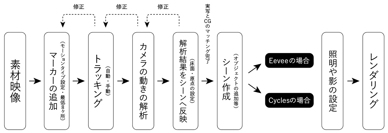
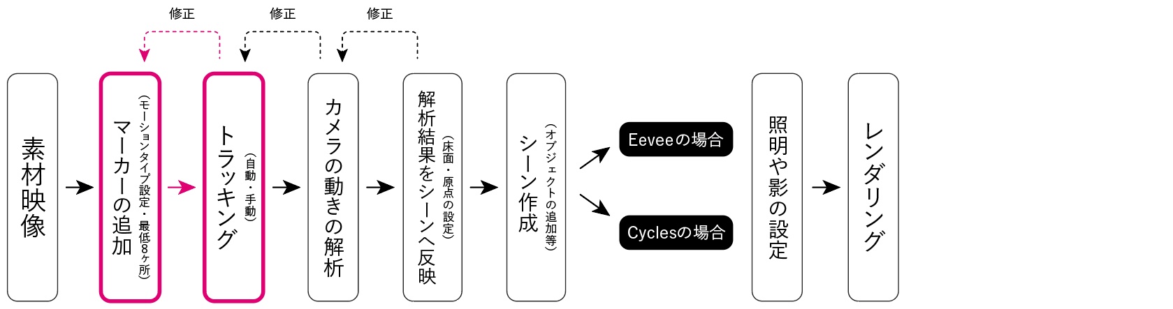
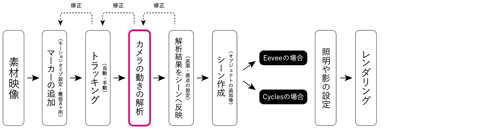
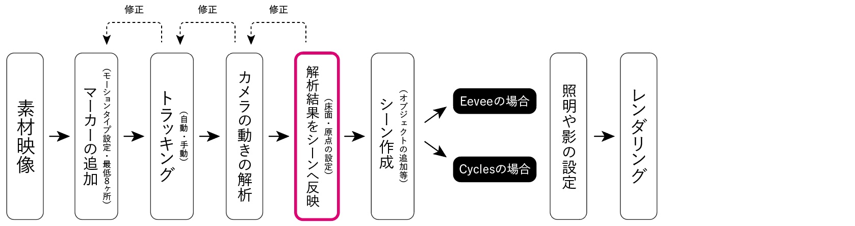
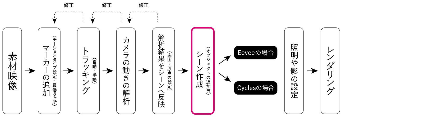
2. Workflow
Note: There’s a lot to learn and a lot of trial and error involved
3. Preparing the Materials
3.1 Downloading Footage
Distribute via the kibaco announcement. Unzip hinoA_20240917.mp4.zip. File name: hinoA_20240917.mp4
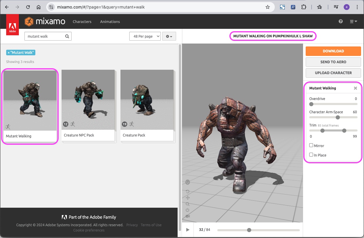
3.2 Downloading Mixamo Characters
- https://www.mixamo.com/
- Character: PUMPKINHULK L SHAW
- Animation: Mutant Walking
- Overdrive: 0
- Character Arm-Space: 60
- Trim: 0-99
- In Place: Unchecked (Root Motion)
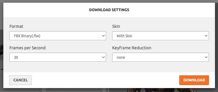
Rename the download file so that the settings are clear.
- (Before) Mutant Walking.fbx → (After) Mutant Walking_RootMotion_0to99.fbx
4. Setting Up Blender
4.1 Launching Blender
Launch Blender and delete the cube.
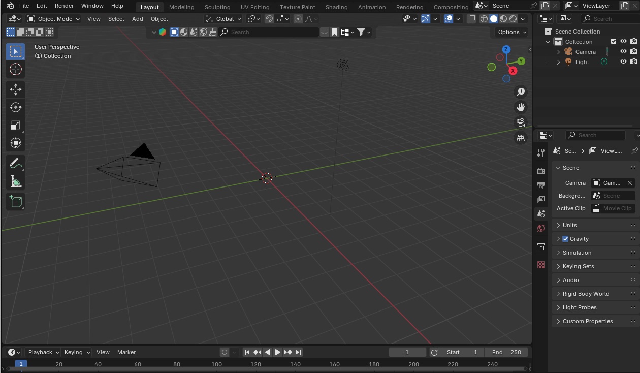
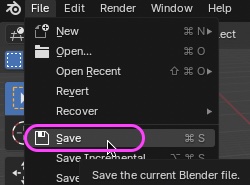
Save the project file to any location.
4.2 Various Blender Settings (Optional)
4.2.1 Display Settings for Grids and Axes
After configuring the settings below, save the presets and preferences as needed.
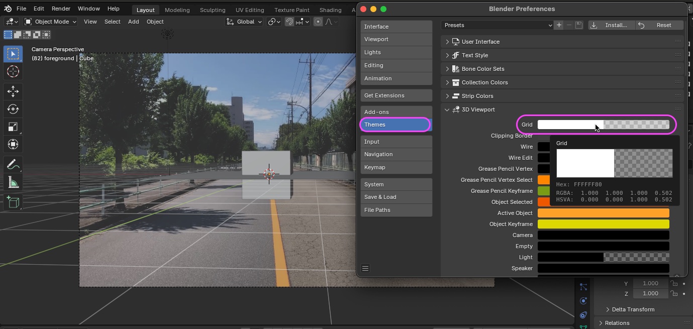
- Grid
- Preferences > Themes > 3D Viewport
- Change the grid color and alpha. *Changing the alpha might be useful (see figure below)
- You can increase the number of grid lines by increasing the Unit value as needed (see figure below)
- Preferences > Themes > 3D Viewport
- Axis (Changing this doesn’t make much difference since the grid color has a greater impact)
- Preferences > Presets > Use Interface Axis & Gizmo Colors
- There is no Alpha option
- Preferences > Presets > Use Interface Axis & Gizmo Colors
4.2.2 Setting the Number of Undo Steps
Increase the number of undo steps as needed.
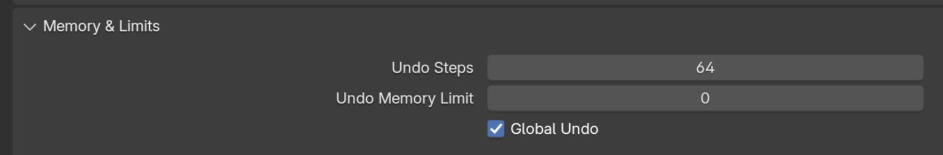
- Preferences > System > Memory & Limits
- Undo Steps: 64 (default is 32; avoid setting it too high as it consumes memory—keep it around 100)
- Global Undo: ON (default is OFF; the manual recommends setting this to ON)
- Reference)
5. Preparing for Motion Tracking
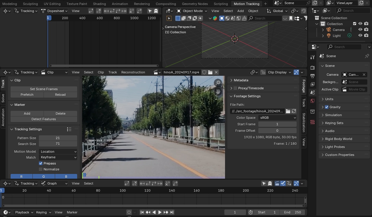
5.1 Displaying the Motion Tracking Workscape
Click the “+” (Add Workspace) button on the far right of the workspace.
Add VFX > Motion Tracking from the menu.
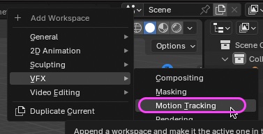
The Motion Tracking Workspace appears.
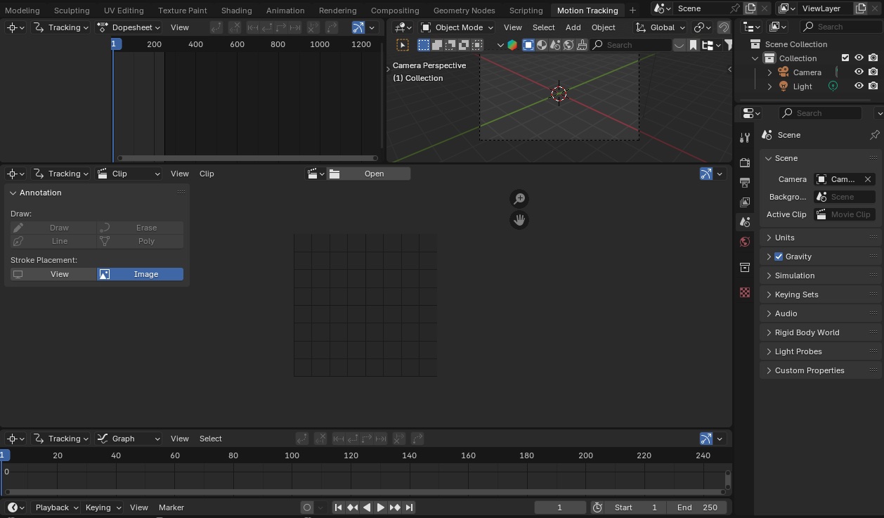
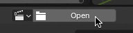
5.2 Importing Footage
Click “Open” in the center of the Movie Clip Editor (middle panel) to load hinoA_20240917.mp4.
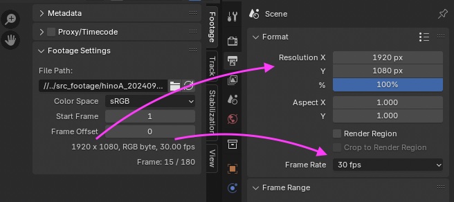
5.3 Match Output Properties to Footage Settings
- Check the resolution (1920 x 1080) under Footage > Footage Settings in the sidebar.
- Go to Output Properties > Format and ensure the X and Y resolutions match (this step is unnecessary in this case since they are the same).
- Check the frame rate (30 fps) under Footage > Footage Settings in the sidebar.
- Go to Output Properties > Format and change the Frame Rate to 30 fps.
- Go to Output Properties > Format and change the Frame Rate to 30 fps.
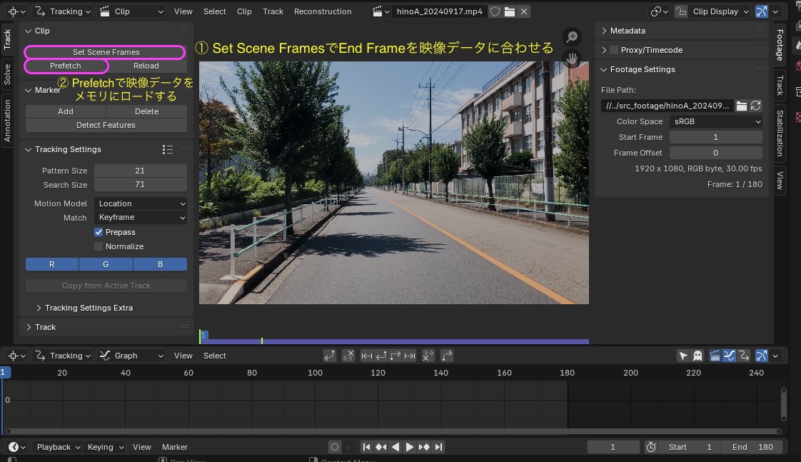
5.4 Configuring Track Clip
- Click “Set Scene Frames” to automatically adjust the End Frame to match the video data (250→180)
- Click “Prefetch” to load the video data into memory
- This allows the video to be played back in real time
- If the resolution is high, only a portion of the video will be played → Additional memory is required
- Adjust the video preview as needed using the scroll wheel (to scale) or drag the wheel (to move) for optimal viewing
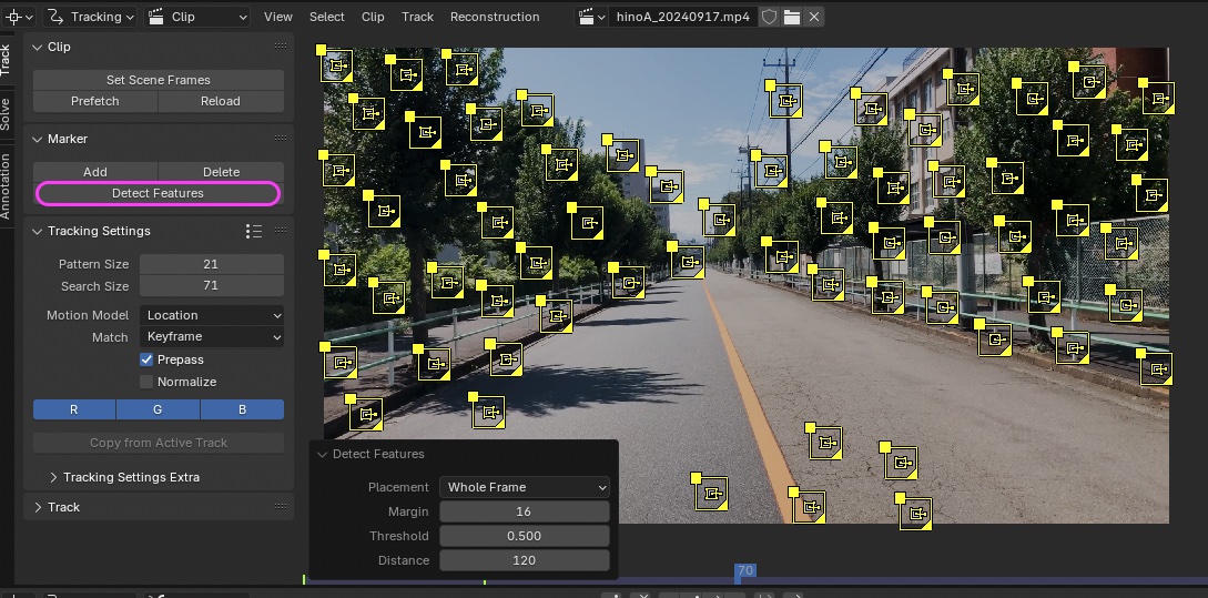
6. Adding Markers and Tracking (Automatic)
*Explanation only
- Automation is not a panacea; it is essentially the automation of manual processes, and in fact, it can lead to numerous errors.
- It is also important to understand that the process of correcting or deleting errors during manual editing must be automated as well.
- This approach is best suited for experts; beginners are more likely to succeed by carefully tracking each item manually.
For your reference
7. Adding Markers and Tracking (Manual)
Note: This will require a fair amount of trial and error.
7.1 Scope of Work
7.2 Tracking Settings
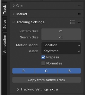
The following settings remain unchanged from their default values.
- Pattern Size (size of feature points): 21 px *Left at default value
- Search Size (size of feature point search area): 71 px *Left at default value, but may be adjusted manually if tracking stops
- Motion Model: Location
- Note: If camera movement is involved, Rotation or Scale may also be included. This did not work well with the footage used in this test.
- Note: Perspective and Affine are likely intended for object tracking
- Match: Keyframe
- Note: Using “Previous Frame” did not work well in this case, but depending on the footage, “Previous Frame” may be better. This is particularly true when the “Floor” setting does not work properly.
- Prepass: Check the box
- Normalize: Uncheck the box
- Note: While “Normalize” is commonly used on YouTube, in this footage…
7.3 The First Maker
7.3.1 Tips for Placing Markers
- High-contrast objects
- Not concentrated in a single area on the screen (i.e., scattered throughout the screen)
- Objects both near and far (i.e., varying distances)
- Be aware that vegetation and its shadows may move due to wind
- Fences are not suitable as marker locations because the background image changes when the camera moves
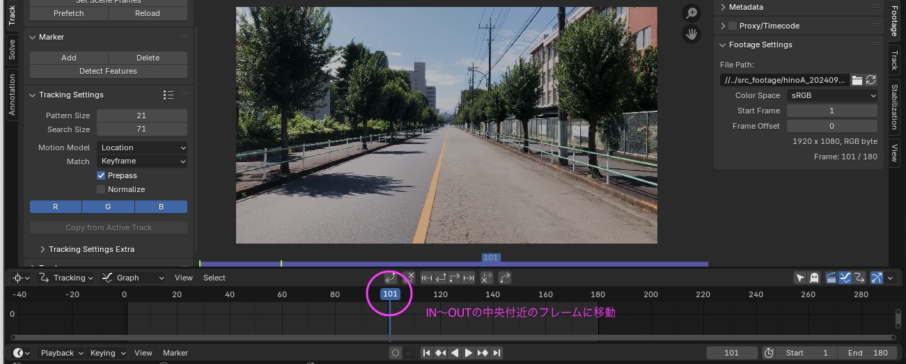
7.3.2 Move the time indicator to the center of the IN–OUT range
- Check the parts of the video that are always visible from the IN to the OUT
- If you add markers to areas that disappear as the camera moves, tracking will only be performed up to that point
- While this data is still used for tracking, it becomes less accurate; therefore, when tracking with a small number of points, add markers to points that are always visible.
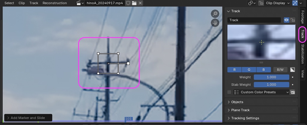
7.3.3 Adding and Tracking the First Maker
- Press Cmd + left-click at the intersection of the utility poles to add a marker.
- You can drag near the center of the marker to fine-tune its position.
- You can view the pattern (image of feature points) in the Track tab.
- If you make a mistake, you can delete it by pressing the X key.
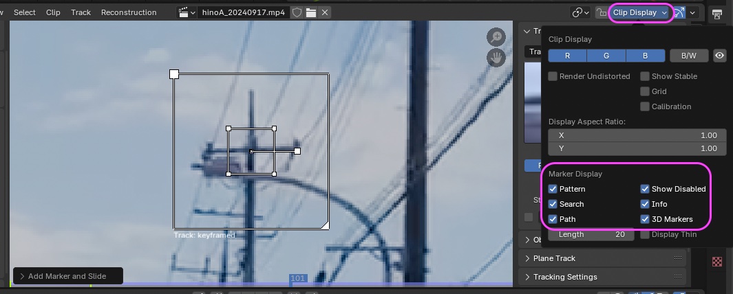
To display additional information, click “Clip Display” and check the boxes for “Search” (OPTION+S), “Info,” and “3D Markers” in the “Marker Display” section.
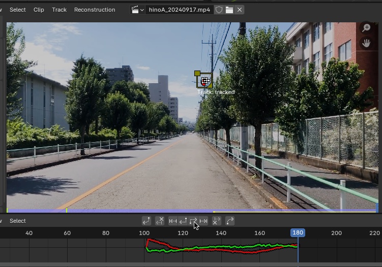
Click the icon below to track forward.

- Tracking is performed as shown in the figure below.
- If tracking stops during the process, go back one frame, adjust the Search Size, and retry tracking.
- If the point is misaligned at this point, correct it.
Move the time indicator to the frame where “Pattern Size” (or “Search Size”) is displayed.
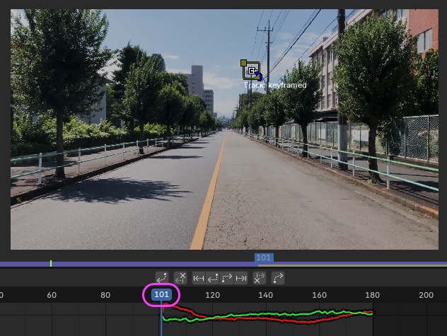
Press the forward tracking button.

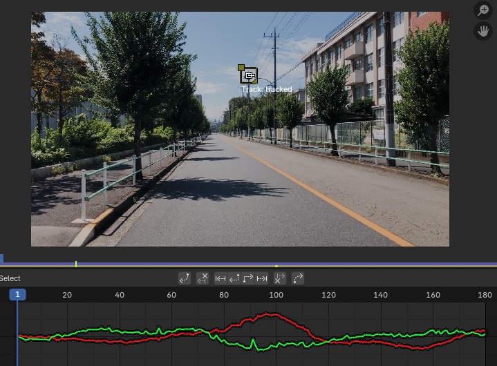
If tracking stops midway, adjust it until all frames are tracked, as shown in the figure below.
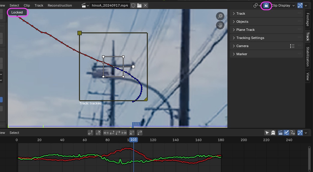
7.4 Locking the Maker Display
Click the lock icon on the left side of the Clip Display (see figure below) or press the L key to have the playback preview follow the selected Maker.
This view allows you to check the tracking status.
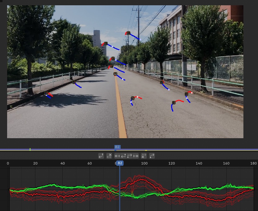
7.5 Adding the Remaining Markers and Tracking
- Motion tracking requires at least 8 markers
- Each time, move to a frame near the middle of the IN–OUT range, then track forward and backward
- Add markers and perform tracking at the 10 points shown in the figure below.
- Analysis is possible with a minimum of 8 markers, but we have also added markers required for setting the Floor and Origin.
- This is the result of trial and error, so it may vary depending on the footage.
- Markers for the center line and the floor are particularly prone to misalignment, so track them while making repeated adjustments.
8. Solve (Analysis of Camera Movement)
8.1 Current Work
8.2 Camera Sensor Size and Focal Length
Note: Regarding the camera’s focal length, since automatic analysis yielded better results, we will follow the method described in Section 8.2.2.
8.2.1 Specifying Depth of Field (Introduction Only)
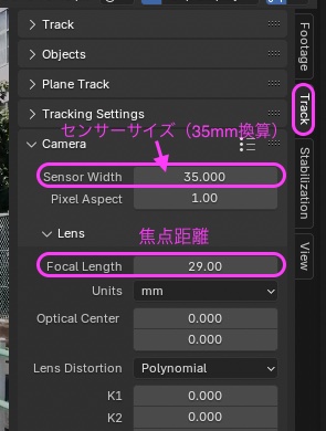
Change the values in the “Track” tab of the right sidebar to the values shown below.
- Sensor Width: 35mm
- Focal Length: 29mm (35mm equivalent)
*The camera used here is the wide-angle camera of the two cameras on the iPhone 8 Plus (values researched online).
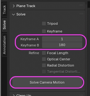
Next, change the values in the left toolbar as follows, then click “Solve Camera Motion.”
- Keyframe A is the frame at the IN point
- Keyframe B is the frame at the OUT point
These do not necessarily have to be the IN and OUT points; any two frames where the camera has moved and the composition has changed significantly will work.
 For this exercise, follow the method described in section 8.2.2 below
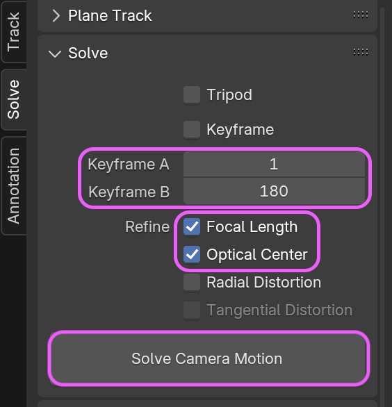
8.2.2 Automatic Depth-of-Field Analysis
- Align Keyframe A and Keyframe B with the IN and OUT points
- Use the following settings here
- Keyframe A: 1
- Keyframe B: 180 Note: If not aligned with the OUT point, there is a high probability that the Floor setting will result in an error
- If analysis accuracy is low, try using different frames
- Use the following settings here
- Focal Length: ON (Automatic depth of field analysis)
- Optical Center: ON (Automatic optical center analysis) Can be specified manually later
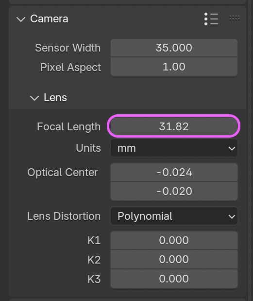
After running “Solve,” you can view the analysis results by going to Sidebar > Tack tab > Camera > Lens > Focal Length.
In the figure below, the value is 31.82 mm, which differs from the camera’s specified value of 29 mm. It is difficult to determine which is correct, but since lenses and CCDs may incorporate some sort of filter, if that is having an effect, the value that deviates from the specified value might actually be closer to the actual condition.
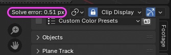
8.3 Solve Error
“Solve error” appears in the sidebar (see figure below). A lower value is preferable, but a value of around 0.5 or less is acceptable.
If the error value is high, review the tracking points and perform a reanalysis.
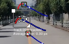
After analysis, the average error for each marker is displayed below the search area.
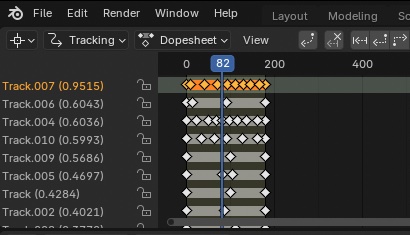
The Tracking panel in the Movie Clip Editor displays track information sorted by severity of error. Select and delete tracks as needed.
Please note that there are some quirks when selecting markers in the previews of the Movie Clip Editor’s Tracking panel and Clip panel (since they do not synchronize, you may need to deselect the marker in the Clip panel first, for example).
-
Note: You can set the “Solve” range using the area drawn in the “Annotation” tab on the left, but making it too narrow will degrade the analysis results. Since you need to redraw the annotation for each frame, this is difficult unless you are an expert.
-
Tips for Troubleshooting
- Try changing keyframes A and B (e.g., 10 and 170)
- Set the focal length to automatic or fixed
- Delete tracks with many errors and start over
- Redo all tracks from the beginning
9. Applying Analysis Results to the Scene
9.1 Scope of Work
9.2 Applying Changes to the Scene
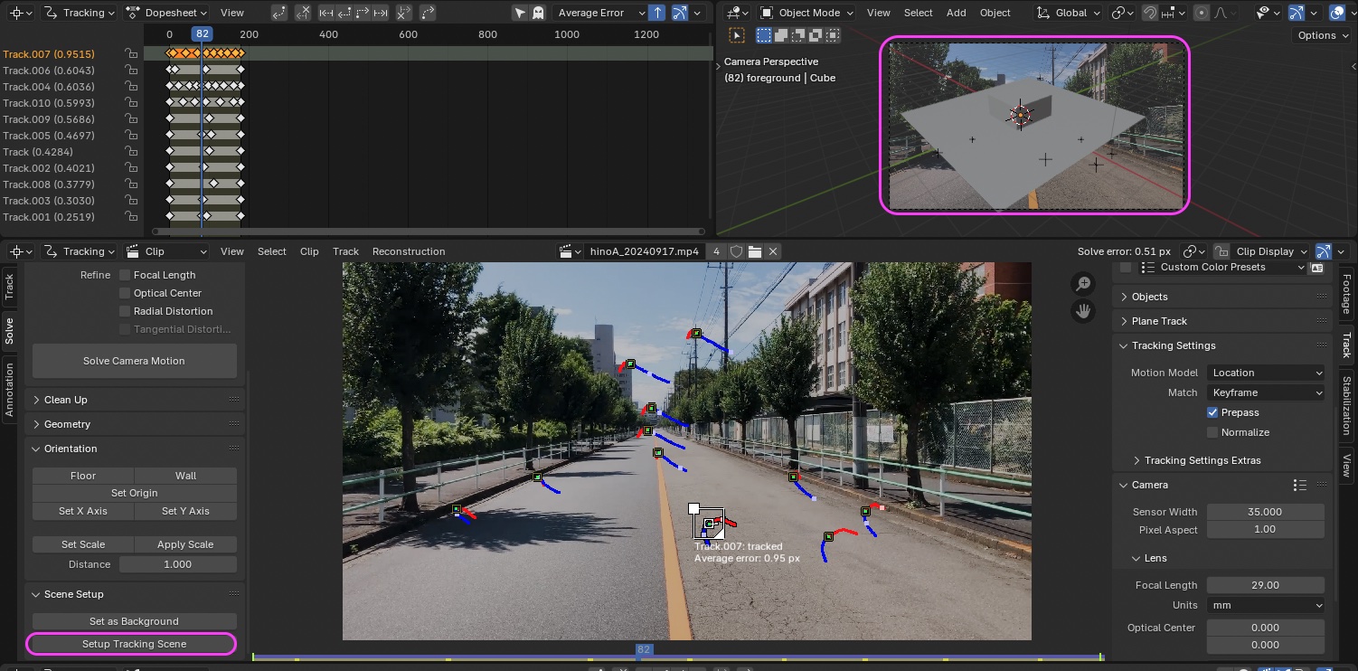
Click the “Setup Tracking Scene” button in the Solve panel > Scene Setup.
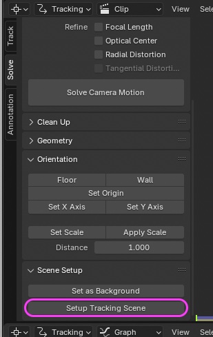
The tracking results are applied to the scene’s Camera, and the video (opacity 50%) is set as the Camera’s Background.
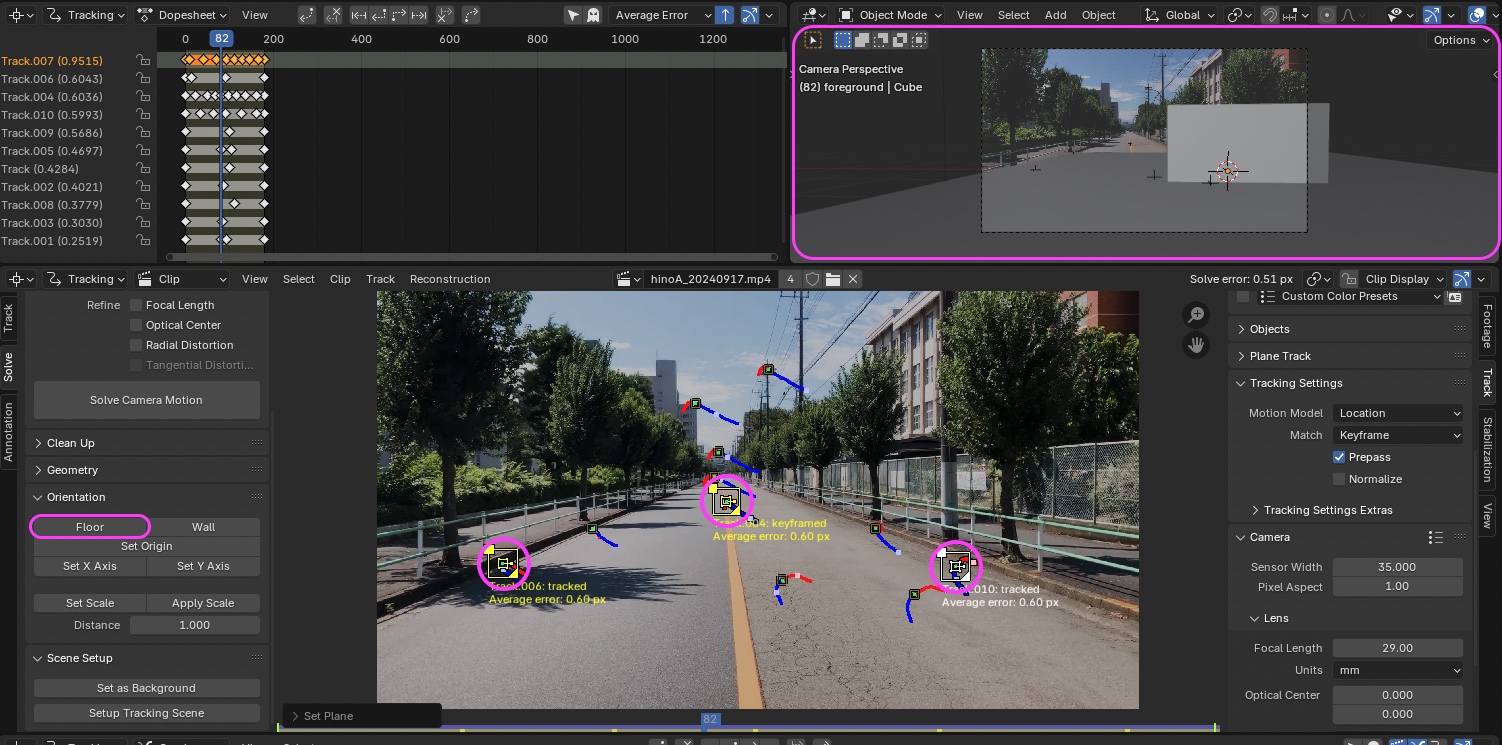
9.3 Floor Settings
- Select three markers while holding down the SHIFT key
- Click Solve Panel > Orientation > Floor
- The origin will move and rotate to adjust the orientation, as shown in the upper right of the image below
If a floor configuration error occurs
- Three tracks with boundles are required to orient the floor
- The tracks have not been solved, or you have selected a track with a large error
- Try changing the keyframe and resolving
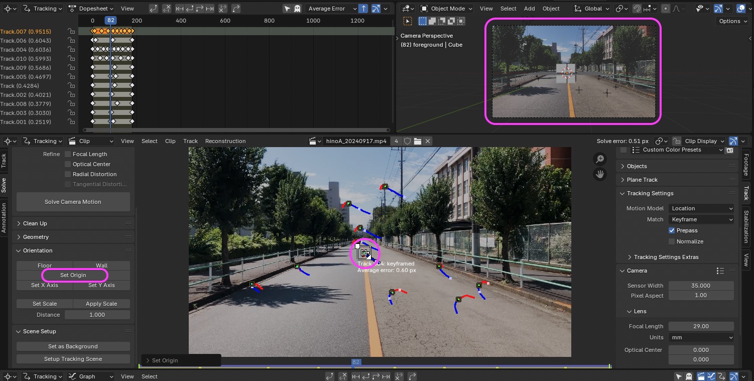
9.4 Origin Settings
- Select the marker on the center line
- Click Solve Panel > Orientation > Set Origin
- The origin will move as shown in the upper right of the figure below
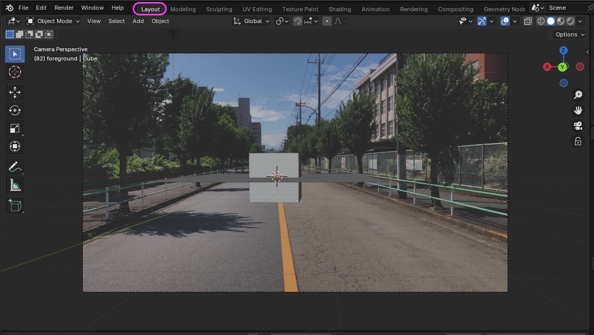
9.5 Preparing to Create a Scene
This task requires a bit of know-how
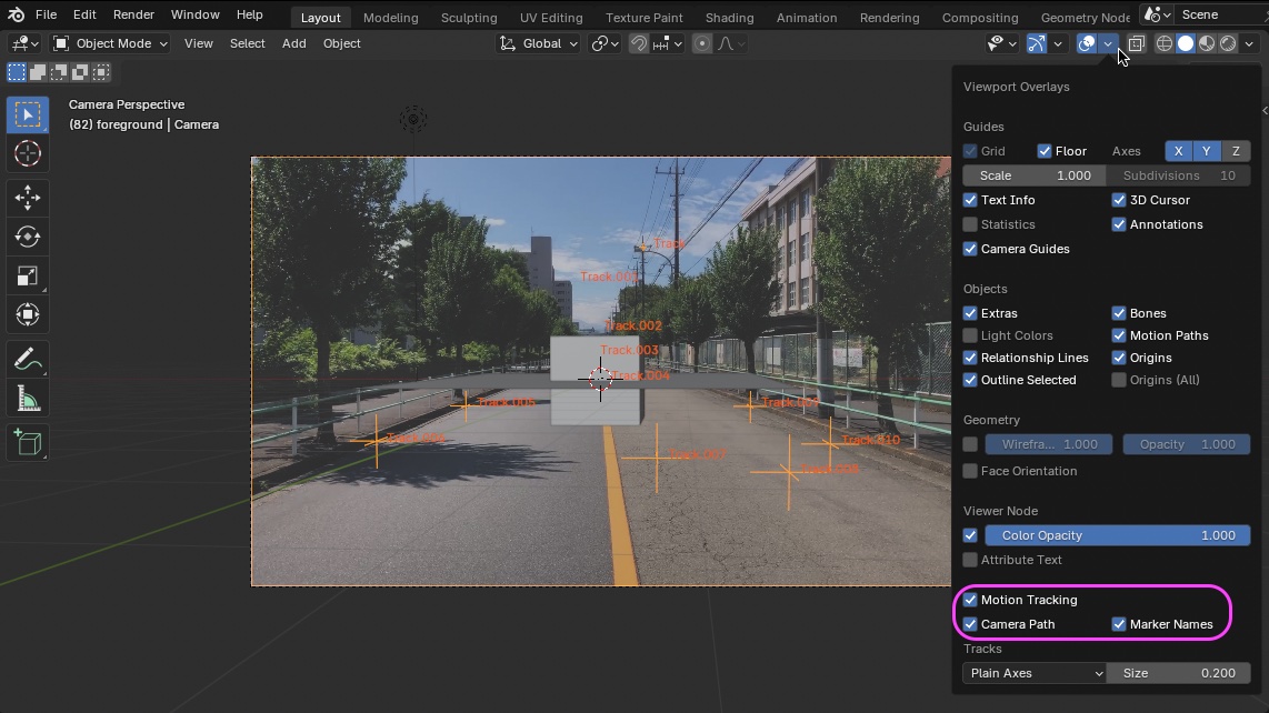
Switch to the Layout workspace.
Check the following options under “Viewport Overlays”:
- Motion Tracking
- Camera Path
- Marker Names
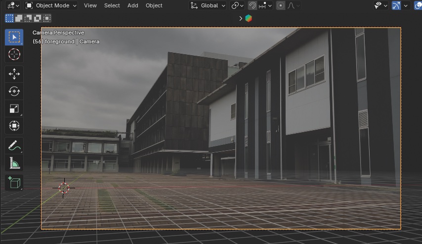
Change the view to check the markers and other elements.
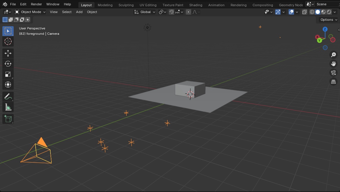
If you change the view in the 3D Viewport, the background image will not be displayed, so click the icon shown below to return to the Camera View.

Preferences > Themes > 3D Viewport > Increase the grid opacity (optional). To revert, click Reset in the upper-right corner of the image below.
- Hide the Cube.
- Click the edge of the camera frame in the Outliner or the 3D Viewport to select the camera.
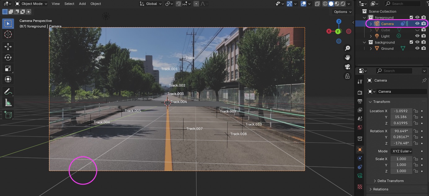
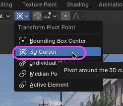
Change the Transform Pivot Point from the Median Point to the 3D Cursor.
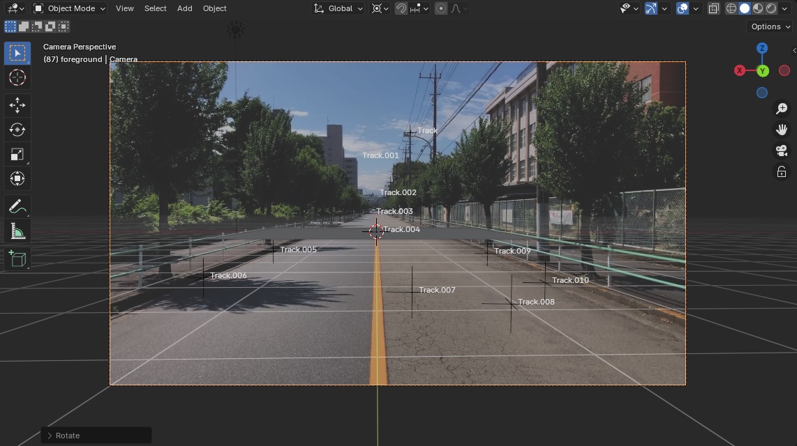
- Use the R and Z keys to rotate the camera horizontally around the 3D Cursor.
- Adjust the camera so that the Y-axis or X-axis aligns with the center line, as shown in the figure below.
- If the rotation increment is too large, hold down the SHIFT key to make fine adjustments.
- Beginners should avoid the following:
- It can be difficult to tell whether the movement is a tilt or a general up/down shift, which may result in significant misalignment.
- If necessary, use R and Y to rotate the camera in the tilt direction, or G
- Moving the time indicator will help you gauge the degree of misalignment on the tilt side.
- It can be difficult to tell whether the movement is a tilt or a general up/down shift, which may result in significant misalignment.
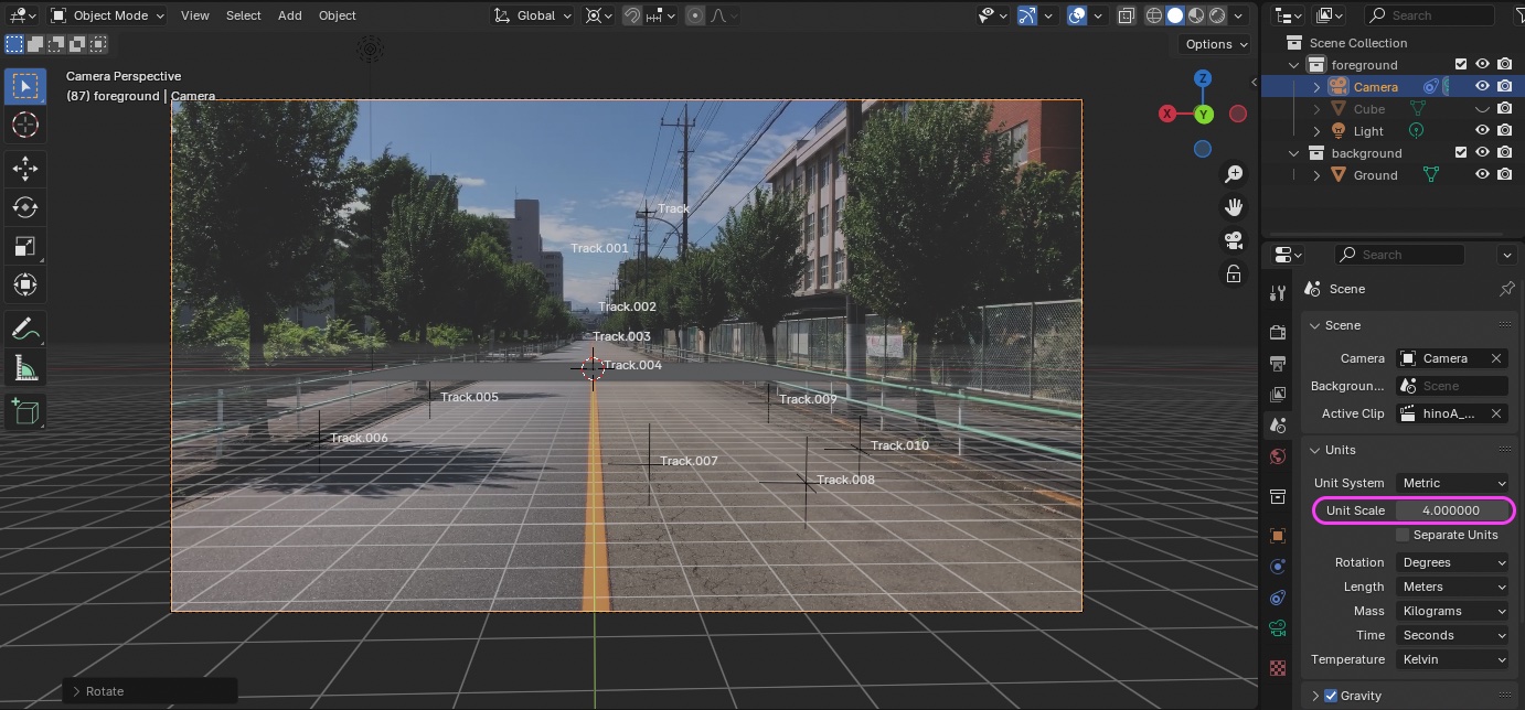
If necessary, reduce the value under Viewport Overlays > Guides > Scale (to around 0.4) to make the grid finer.
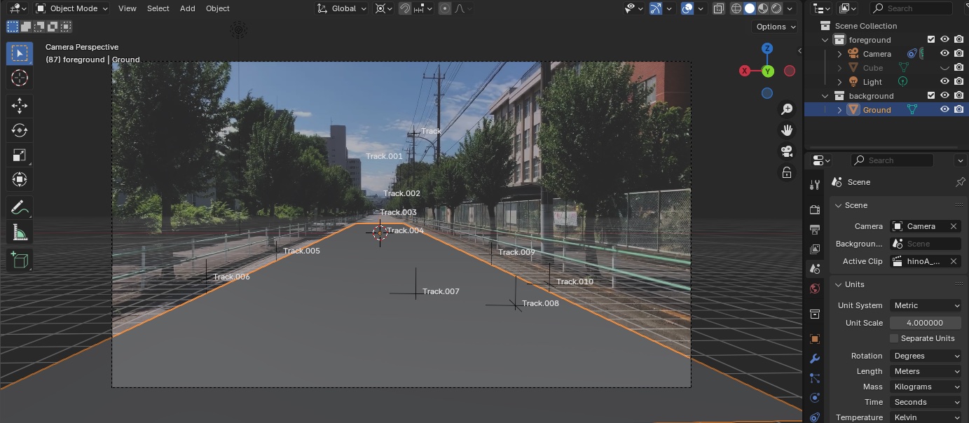
Select the Ground Plane (which corresponds to the “Floor”), then use S and X or Y to create a pseudo-road.
Play the scene to verify that the road is roughly aligned. If it is significantly off, it’s better to start over by adding markers. If you have some experience, you can adjust it by rotating the camera, but beginners may end up making it even more misaligned.
If necessary, reset the Transform Pivot Point to the Median Point.
- Nakayasu’s Personal Notes (Blend files) blender_files_tracking_test3 > hinokaijuA_trackingTest3_w9.blend
10. Creating a Scene
10.1 Scope of Work
10.2 Load PUMPKINHULK (optional)
Prepare the Mutant Walking_RootMotion_0to99.fbx file (renamed) that you downloaded in Section 3.2.
Import it by selecting File > Import > FBX or by dragging and dropping it into the 3D Viewport.
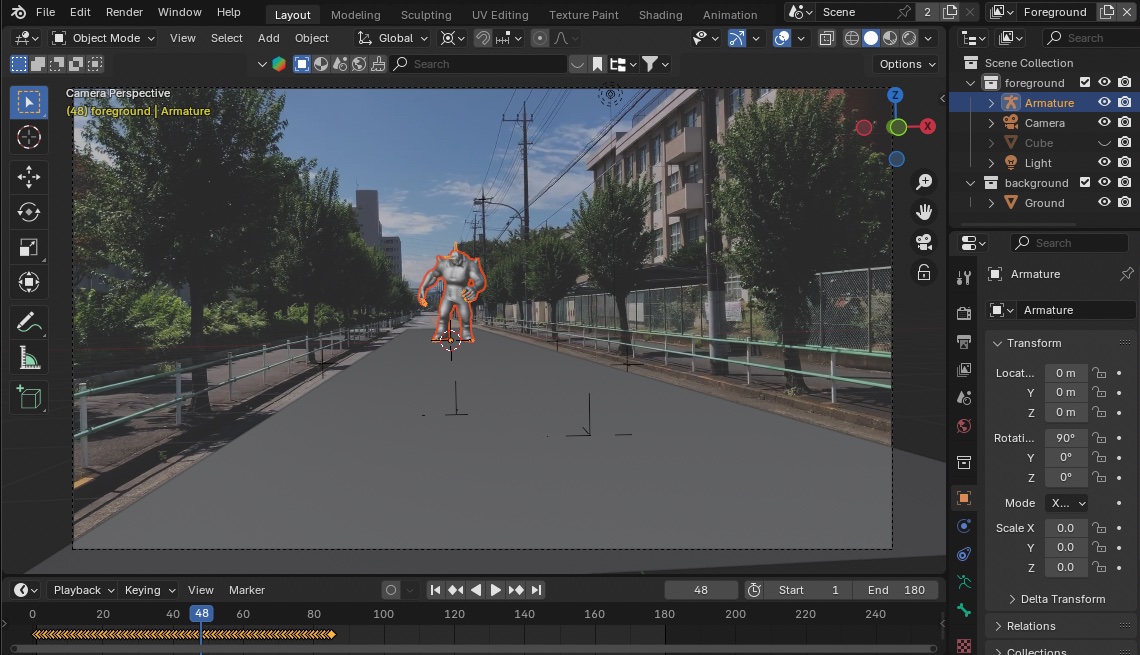
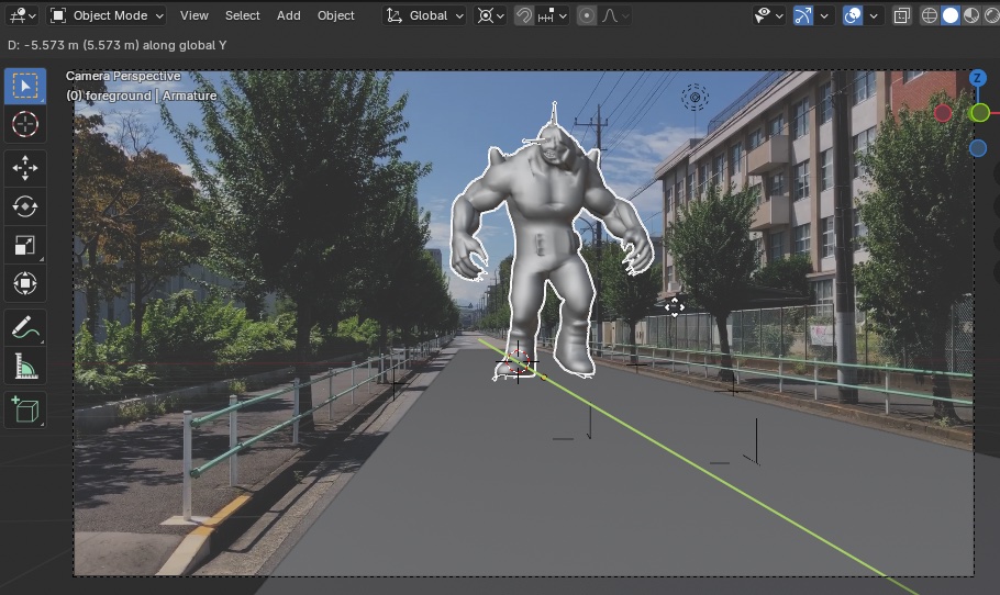
10.3 Adjusting Walking Direction and Size
- Size adjustment: Scale with S
- Walking direction: Rotate with R, Z, and -90
- Starting position: Move with the G key
- You can also select the camera and use the G and Y keys For now, a rough estimate is fine. We’ll readjust after setting up the shadows and lighting.
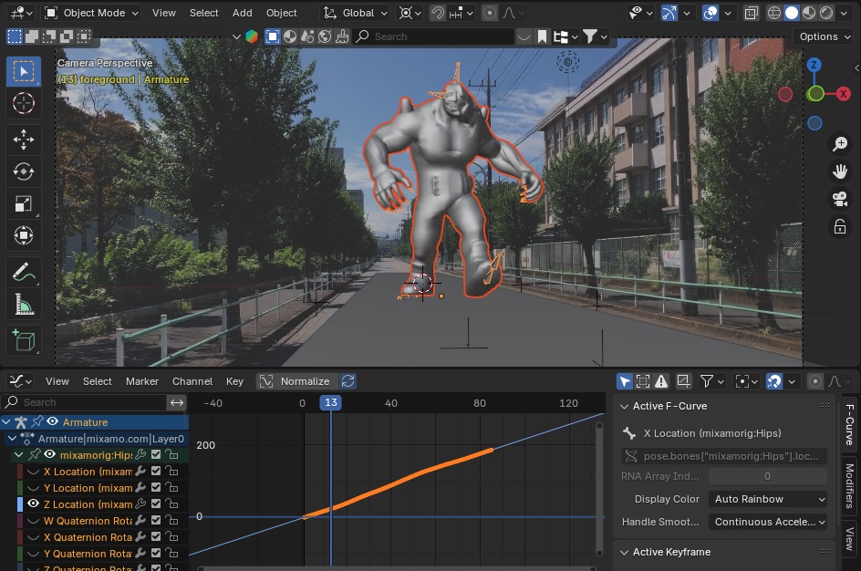
10.4 Loop Animation Settings
In Method 3 of “Multiple Ways to Create Loop Animations for Mixamo Characters,” set up an animation for walking forward. (Practice Progress Note) I have completed the exercise for Method 4 (In Place), but I have not yet done Method 3 (Make Cyclic in Root Motion).
11. Saving a blend file
Since the steps from this point onward differ between Cycles and Eevee rendering, save the blend file at this stage and save a separate blend file for the remaining steps.
- (Nakayasu’s personal note) blender_files_tracking_test3 > hinokaijuA_trackingTest3_w12.blend