Fusion 360 Exercise 7
Updated: 2026-05*

This article was written before 2020. It is kept here as an archive — the content is outdated and some links may no longer work.
Making Glasses
In this exercise, we will create glass in the Sculpt environment.
This document was written in October 2017. Functionality has been verified in Fusion 360 version 2.037.
Extruding a Face and Forming the Outer Surface
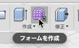
Click the “Create Form” button to enter Sculpt Mode.
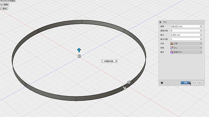
Create > Cylinder. Set the height plane to 1, adjust the height as shown below, and click the OK button.
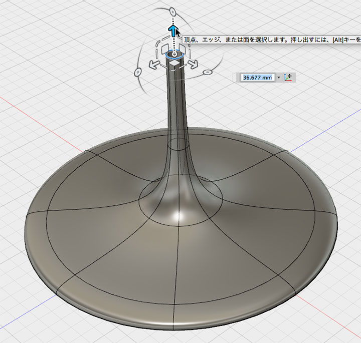
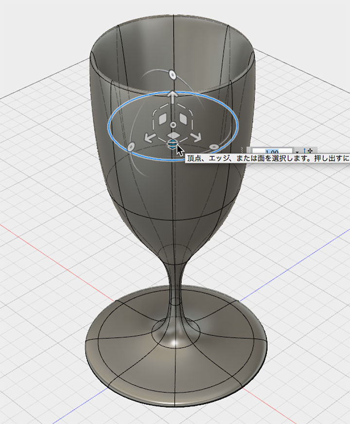
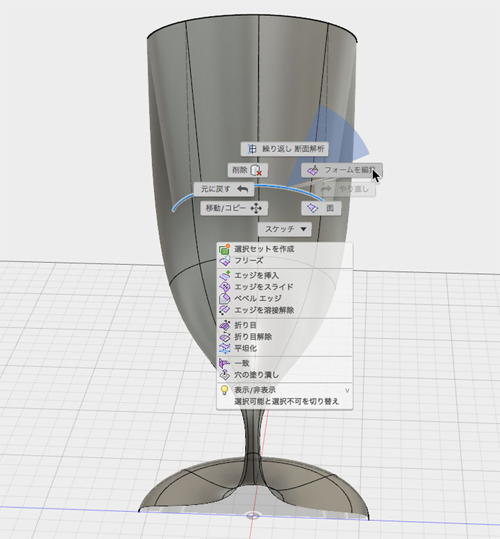
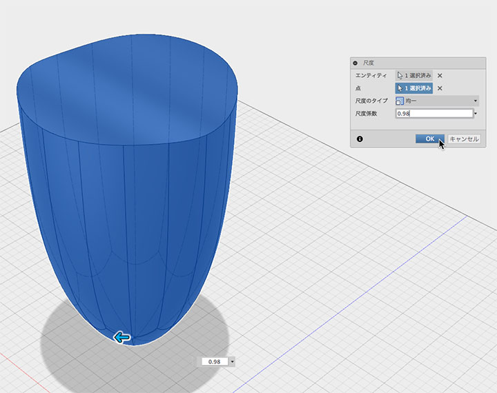
Right-click the top edge to enter form editing mode. Hold down the ALT key and drag the horizontal scaling handle.
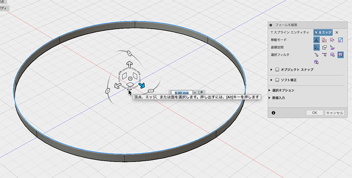
Drag toward the shrink direction and extrude the face as shown below.
Extrude (ALT + drag).
Drag to scale.
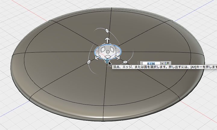
Extrusion.
Extrusion.
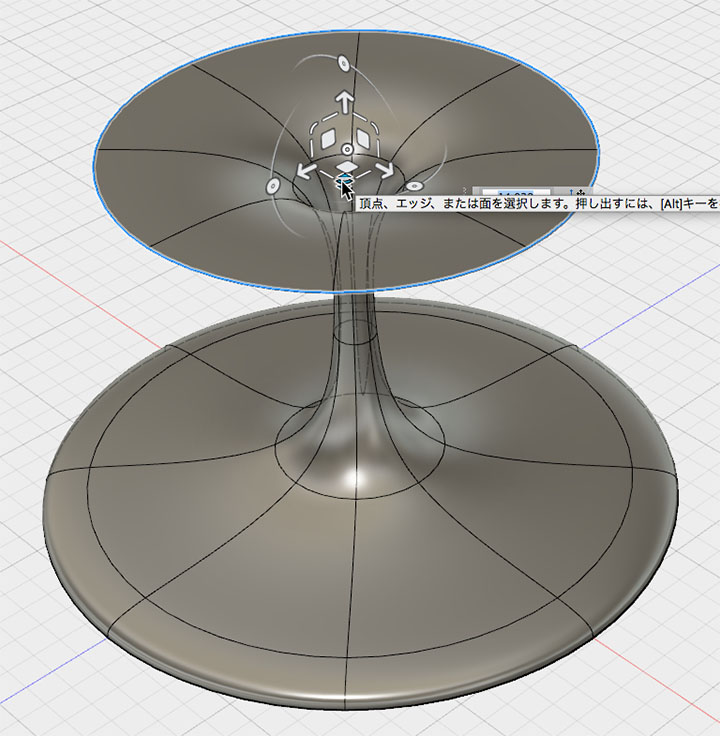
Move.
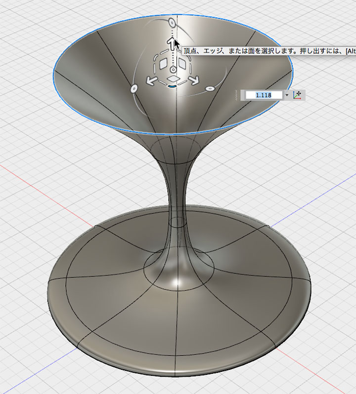
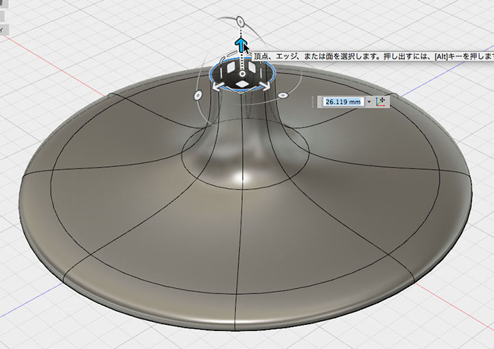
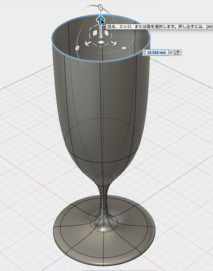
Extrusion.
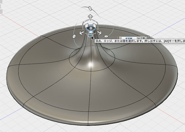
Push out, fold back, then shrink.
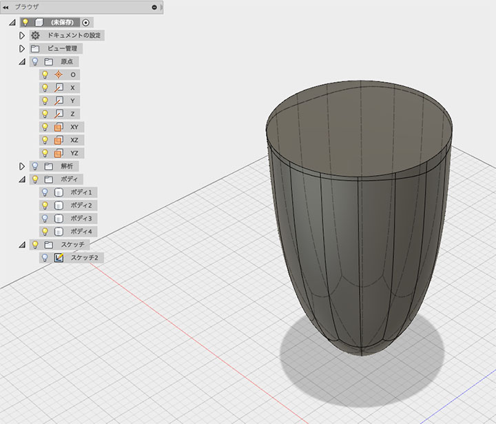
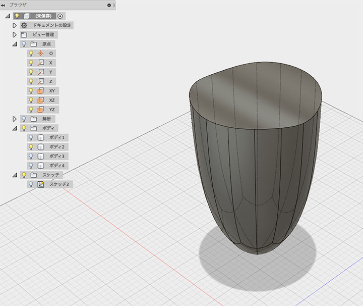
Creating Creases
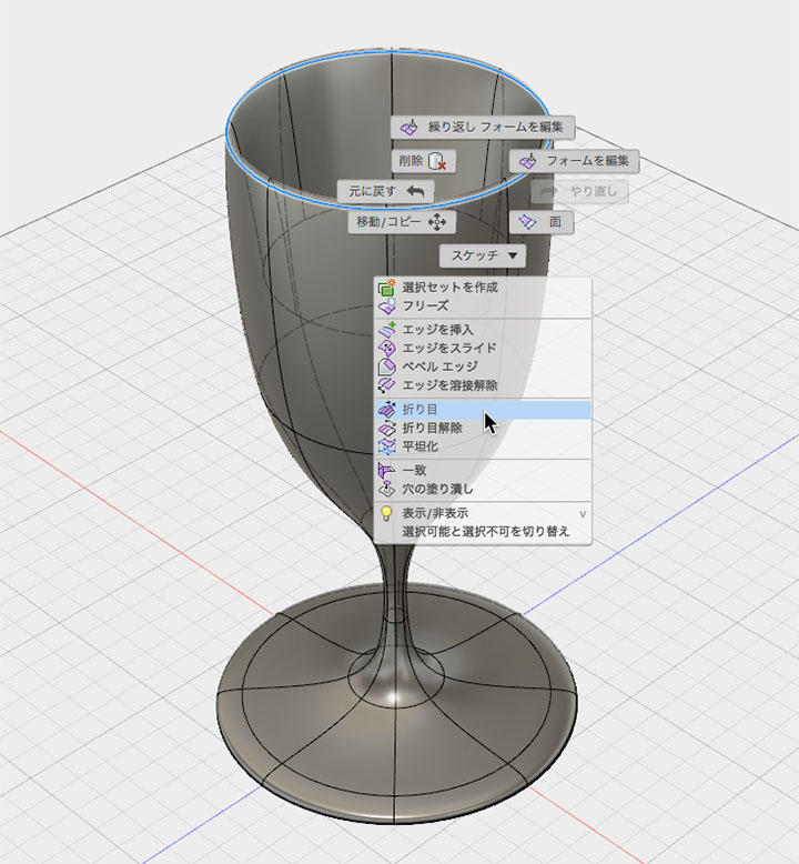
Ultimately, applying a fillet in Model mode produces a smoother curve than the sharp curves of a T-spline, so a crease is created.
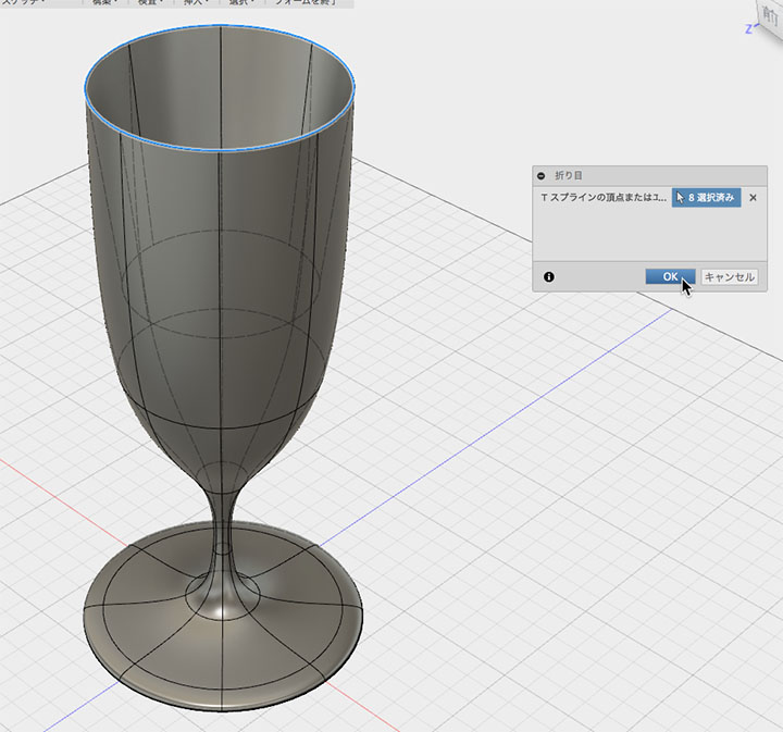
Right-click the top edge to set the fold.
Note that the height changes before and after setting the fold.
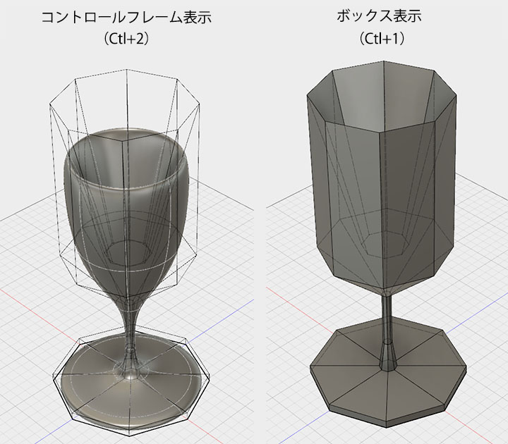
Switch from the standard smooth display (Ctrl+1) to the box display (shown on the right below), which represents the T-spline structure, and the top edge of the box will appear as a crease. You can also change the display mode from Utility > Display Mode.
Cross-Section Analysis and Internal Shaping
Inspection > Use the Cross-Section Analysis Tool. For the cross-section plane, select either the XY plane or the YZ plane.
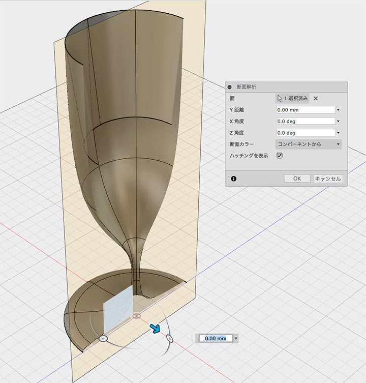
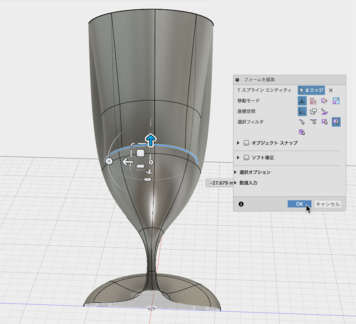
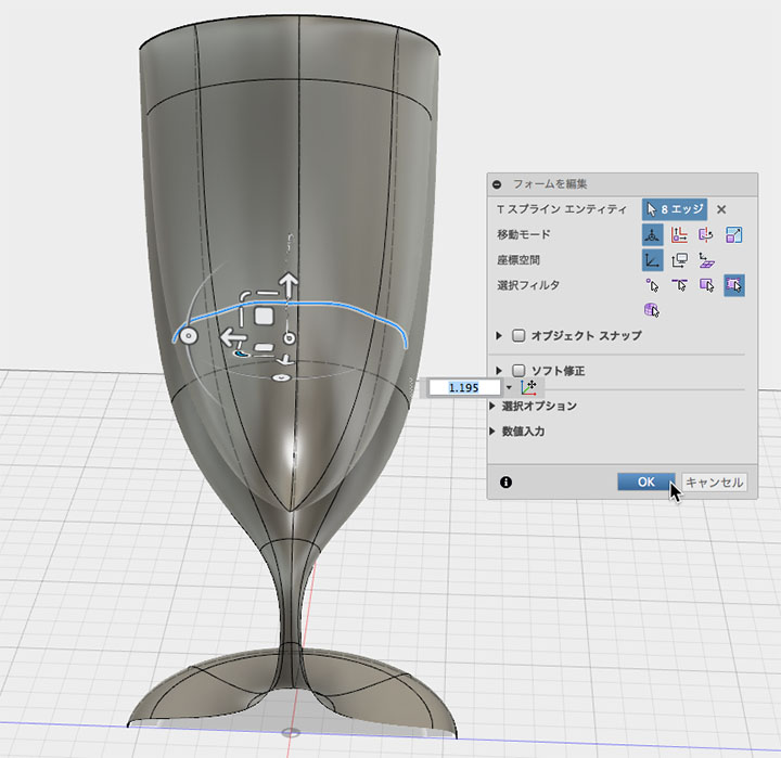
With the cross-section displayed, create the inner surface. Just as you did for the outer surface, use the Form Editor to extrude, scale, and move the faces.
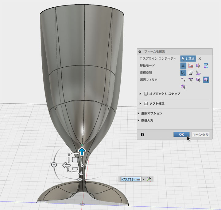
Use the Hole Fill tool to create the inner base. Set the Hole Fill mode to “Collapse.” Check the box for the center vertex of the weld.
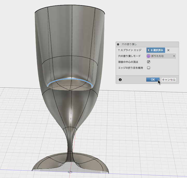
Move the vertex as shown in the figure below.
Make minor adjustments to the internal shape as needed.
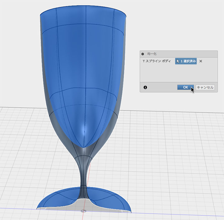
Use the Utility > Uniformize Tool to make an uneven surface uniform.
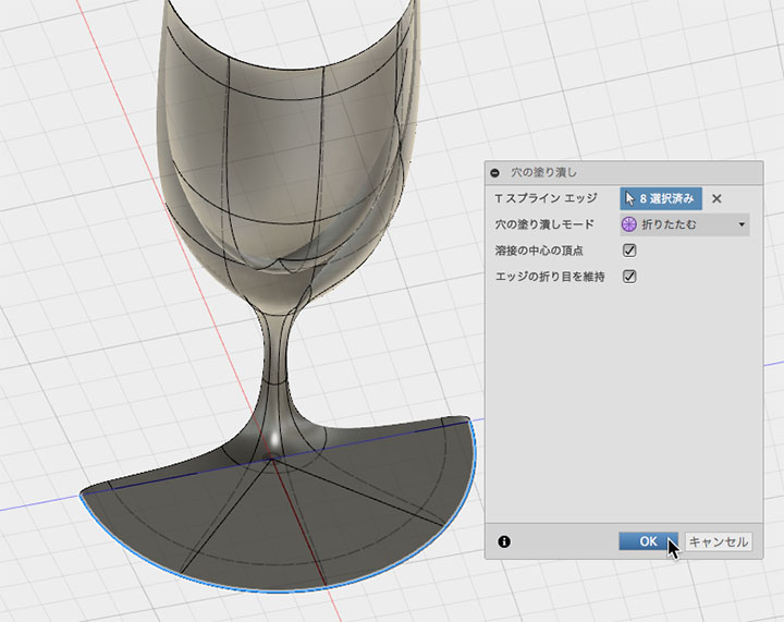
Right-click the bottom edge and use the Fill Hole tool to create the bottom of the glass. Check the boxes for “Keep weld center vertices” and “Keep edge creases,” respectively.
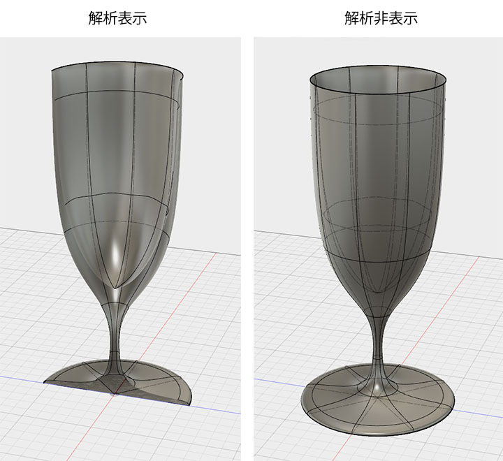
Hide the browser analytics to view the full page.
Changes made using the analysis tools are retained even when you switch back from Sculpt Mode to Model Mode, so you can use them to check cross-sections at any time.
Fillet
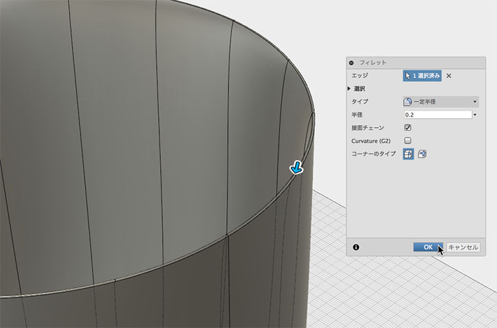
Apply a fillet to the top edge in Model Mode. Since a radius that is too large relative to the thickness will result in significant material removal from the top edge, set a smaller radius. Return to Sculpt Mode as needed to adjust the thickness.
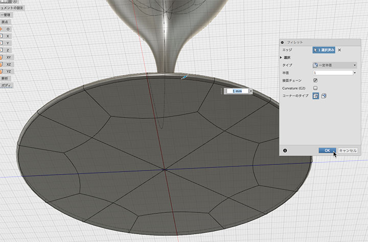
Set the fillet on the bottom surface.
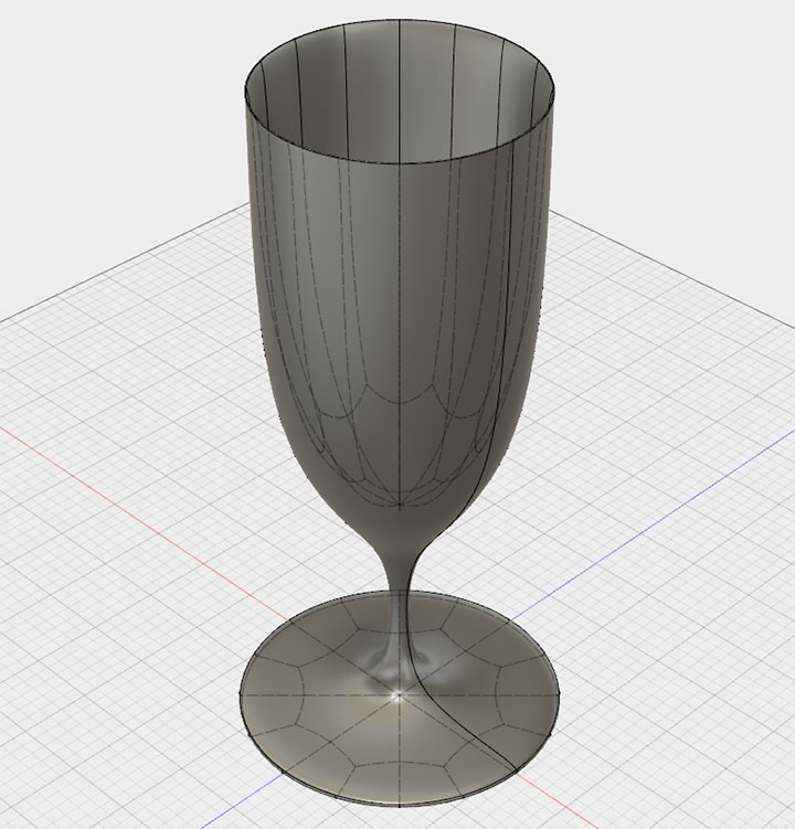
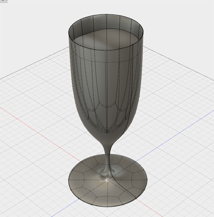
The glass is finished.
Creating Water
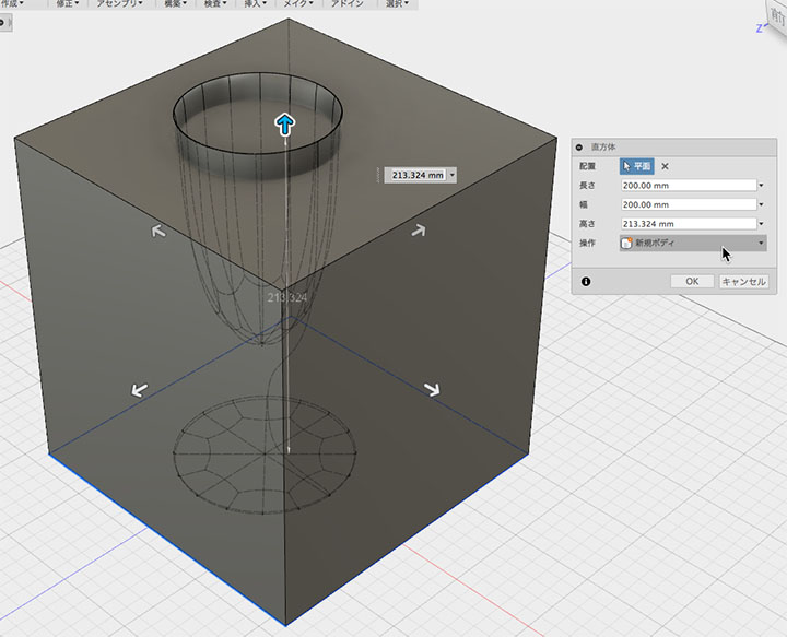
Use the Create > Rectangular Prism tool to create a body as shown in the figure below. Set the dialog option to “New Body.”
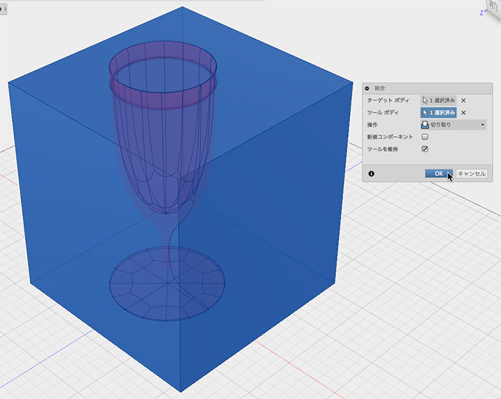
In the Modify > Merge tool, set the target body to a box. Set the tool body to a glass. Check the “Keep tool” box and click OK.
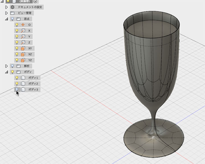
Since the cuboid is separated by a glass panel, hide the outer body from the browser.
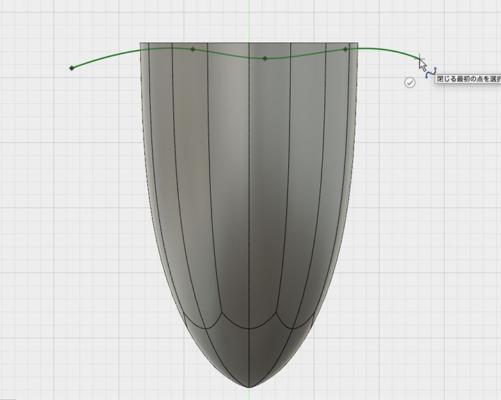
Hide the glass as well, and draw the sketch as shown below.
Modification> Use the Split Tool to select the water body as the body to split. Select a sketch in the Split Tool and click the OK button.

Since the model will be split along the sketch, hide the upper body.
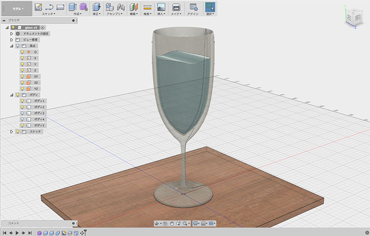
If the glass body and the water body are in close contact, it causes unevenness in the rendered image, so we reduce the size of the water body to create a gap.
The glass and water are ready.
Materials and Rendering
Set the glass material to Glass > Smooth > Glass (Clear).
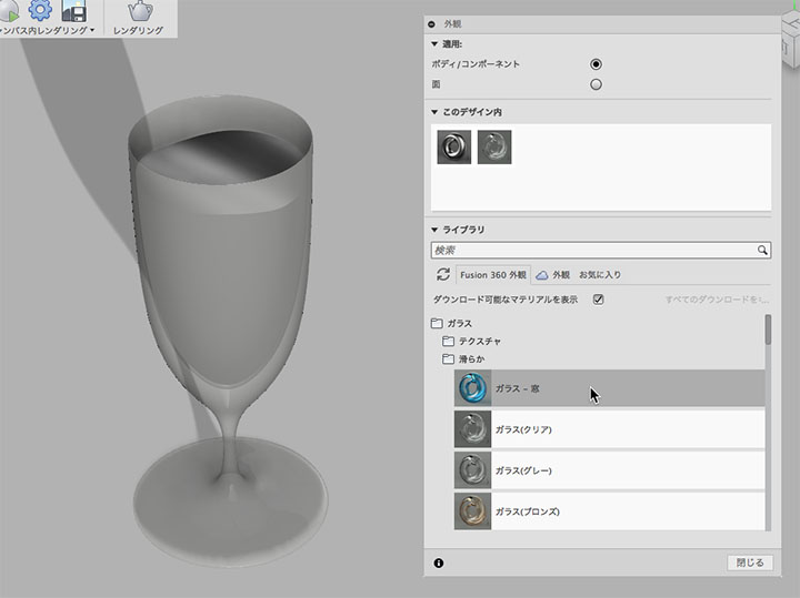
Set the material for the water body to Water > Water-Clear.

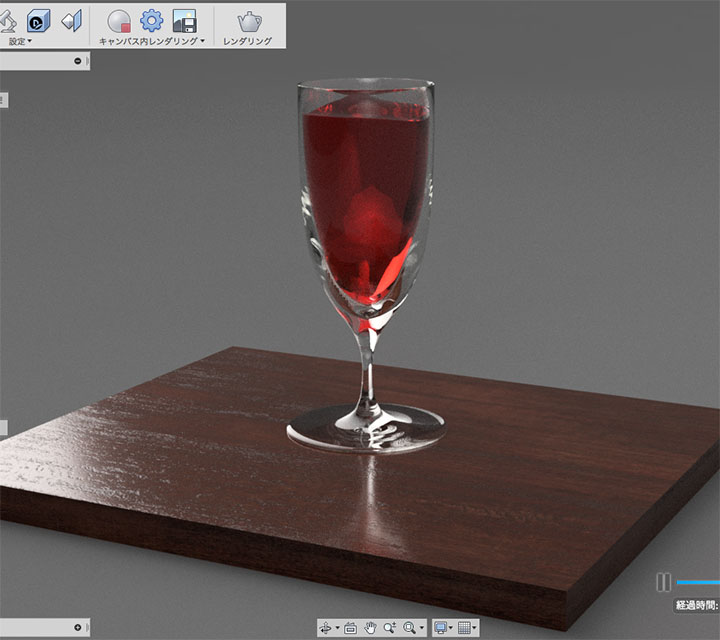
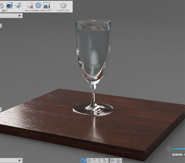
Rendered image.
A rendered image of a water body with the material settings set to Plastic > Transparent > Acrylic (Red).