Arduino + 3-Axis Accelerometer
Updated: 2026-05
This article was written before 2020. It is kept here as an archive — the content is outdated and some links may no longer work.
What Is a 3-Axis Accelerometer?
A 3-axis accelerometer is a sensor capable of measuring acceleration along the X, Y, and Z axes. It is used in mobile phones, game controllers, PC fall detection systems, and robot attitude control. When combined with a geomagnetic sensor, it can function as an electronic compass, and there are various services that integrate it with GPS (Global Positioning System).
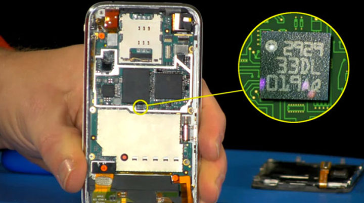
The figure below shows the 3-axis accelerometer built into the iPhone (source).
MEMS (The Technology Behind Accelerometers)
Three-axis accelerometers are made possible by a technology known as MEMS (Micro Electro Mechanical Systems). MEMS is a cutting-edge technology that enables the creation of ultra-small mechanical structures and their integration with electronic circuits; this technology has led to the development of a wide variety of sensors and actuators.
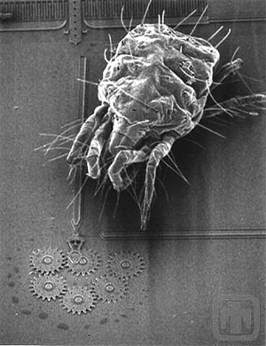
The figure below shows a gear smaller than a tick, created using MEMS technology.
Implementation of a 3-Axis Accelerometer
Continuing from the previous lecture notes on “Arduino + CdS,” we will now add the following components.
Components Used
・3-axis accelerometer KXR94-2050 or KXM52-1050
・Jumper wires: 3 red, 3 black, 3 green
Circuit Diagram
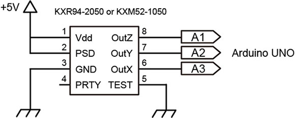
Pin 2 is labeled “Power Shut Down” on the KXM52-1050 and “Enable” on the KXR94-2050, but their functions are identical, and both should be connected to Vdd. Connecting it to GND puts the device into standby mode. While switching this pin can save power, in this case, it should always be connected to Vdd.
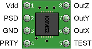
Pin Configuration for 3-Axis Accelerometer (KXR94-2050 or KXM52-1050)
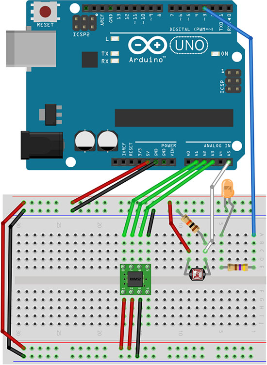
Installation Diagram
Install the 3-axis accelerometer, paying attention to its orientation.
Visualizing Acceleration with Processgin
The analog values from the accelerometer are sent to Processing via serial communication and visualized as a graph.
Please note that you will be using both Arduino and Processing programs at the same time.
1. Preparing the Arduino Sketch
Create a new sketch, copy and paste the code below, and then save the sketch.
// Visualizing acceleration using Processgin (Arduino side)
// December 2017, nakayasu

int sensorValue[3];
int outputValue[3];
int inByte; // Received data

void setup()
{
  for(int k=0; k < 3; k++){ sensorValue[k] = 0; outputValue[k] = 0; } Serial.begin(9600); establishContact(); // Establish serial communication } void loop() { if (Serial.available() > 0) {
    inByte = Serial.read(); // Read from serial
    sensorValue[0] = analogRead(1); // A1 pin input - Z (pin 8 on KXM52-1050)
    delay(10);
    sensorValue[1] = analogRead(2); // A2 pin input - Y (pin 7 on KXM52-1050)
    delay(10);
    sensorValue[2] = analogRead(3); // A3 pin input - X (pin 6 on KXM52-1050)
    delay(10);
    // Convert sensor values from 10-bit (0–1023) to 8-bit (0–255) for serial communication
    outputValue[0] = map(sensorValue[0], 0, 1023, 0, 255);
    outputValue[1] = map(sensorValue[1], 0, 1023, 0, 255);
    outputValue[2] = map(sensorValue[2], 0, 1023, 0, 255);
    // Send via serial
    Serial.write(outputValue[0]);
    Serial.write(outputValue[1]);
    Serial.write(outputValue[2]);
  }
}

void establishContact() { // Continue sending 'A' until serial communication is established
  while (Serial.available() <= 0) {
    Serial.print('A');
    delay(300);
  }
}
Download Sketch Data
Arduino_5-4_VelocityGraph_Arduino.zip (Currently unavailable)
② Uploading the Arduino Sketch
Compile and upload the sketch. Serial communication does not start immediately after the program is uploaded to the Arduino. Serial communication begins only after you launch Processing and the initial data exchange between the sender and receiver is complete.
3. Preparing the Processing sketch
Create a blank sketch, copy and paste the code below, and then save the sketch.
// Visualizing acceleration in Processing (Processing side)
// December 2017, nakayasu

import processing.serial.*; // Load the serial library
Serial myPort;
int[] serialInArray = new int[3];
int serialCount = 0;
int[] xvals;
int[] yvals;
int[] zvals;
int a0 = -1000;
int a1 = -1000;
int a2 = -1000;
boolean firstContact = false;

void setup()
{
  size(600, 400);
  xvals = new int[width];
  yvals = new int[width];
  zvals = new int[width];
  for(int i=1; i < width; i++) {
    xvals[i] = -300;
    yvals[i] = -200;
    zvals[i] = -200;
  }
  printArray(Serial.list()); // Display serial device names in the console
  String portName = Serial.list()[3]; // Serial device number
  myPort = new Serial(this, portName, 9600);
}

void draw()
{
  background(0);
  stroke(60);
  line(0, height/6, width, height/6);
  line(0, 3*height/6, width, 3*height/6);
  line(0, 5*height/6, width, 5*height/6);

  for(int i=1; i < width; i++) {
    xvals[i-1] = xvals[i];
    yvals[i-1] = yvals[i];
    zvals[i-1] = zvals[i];
  }
  // Add the new values to the end of the array
  xvals[width-1] = a2; //X A3 to pin 6 on KXM52-1050
  yvals[width-1] = a1; //Y A2 to pin 7 on KXM52-1050
  zvals[width-1] = a0; //Z A1 to pin 8 on KXM52-1050

  for(int i=1; i < width; i++) { stroke(0, 180, 255); point(i, xvals[i] - 58); stroke(255, 20, 0); point(i, yvals[i] + 73); stroke(0, 255, 0); point(i, zvals[i]+142); } fill(0, 180,255); text("X: " + a2, 10, 15); fill(255, 20, 0); text("Y: " + a1, 10, 15 + height/3); fill(0, 255, 0); text("Z: " + a0, 10, 15+2* height/3); } void serialEvent(Serial myPort) { int inByte = myPort.read(); if (firstContact == false) { if (inByte == 'A') { myPort.clear(); // clear the serial port buffer firstContact = true; // you've had first contact from the microcontroller myPort.write('A'); // ask for more } } else { // Add the latest byte from the serial port to array: serialInArray[serialCount] = inByte; serialCount++; if (serialCount > 2 ) {
      a0 = serialInArray[0];
      a1 = serialInArray[1];
      a2 = serialInArray[2];
      myPort.write('A'); // Send a capital A to request new sensor readings:
      serialCount = 0; // Reset serialCount:
    }
  }
}
Download Sketch Data
Arduino_5-4_VelocityGraph_Processing.zip (Currently unavailable)
④Running the Processing Sketch
The voltage values for the X, Y, and Z accelerations are displayed on a graph. By moving the Arduino acrylic board itself up, down, left, and right, you can understand which direction corresponds to each of the X, Y, and Z axes.
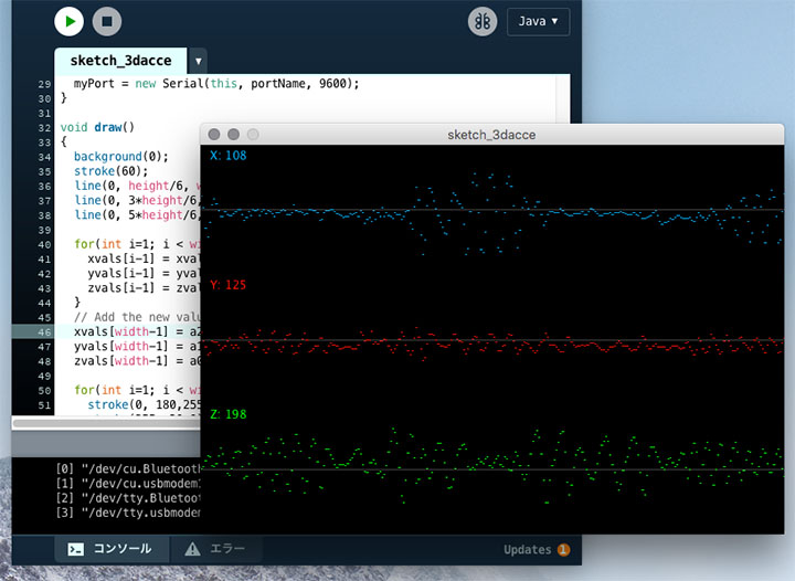
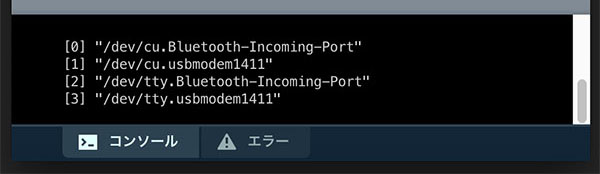
Depending on your environment, you may need to change the serial device number (the number in []) on line 15. You can check the serial device number in the Processing console window, as shown in the figure below. The entry that appears as /dev/tty.usbmodem**** is the Arduino.
Shaking the Cube (Acceleration Values)
1. Preparing and Uploading the Arduino Sketch
We will use the same Arduino sketch as in “4. Visualizing Acceleration with Processing.”
2. Preparing the Processing sketch
Create a new sketch, copy and paste the code below, and then save the sketch.
// Shake the cube (acceleration values) (Processing side)
// December 2017, nakayasu

import processing.serial.*; // Load the serial library
Serial myPort;
int[] serialInArray = new int[3];
int serialCount = 0;
int a0, a1, a2;
boolean firstContact = false;

void setup()
{
  size(640, 480, P3D);
  noStroke();
  colorMode(RGB, 1);
  printArray(Serial.list()); // Display serial devices on the console
  String portName = Serial.list()[3]; // Serial device number
  myPort = new Serial(this, portName, 9600);
}

void draw()
{
  background(0);
  translate(width/2+(a2-127)*4, height/2+(a0-190)*4, (a1-127)*-8);
  rotateX(1); rotateZ(1);
  scale(100);
  beginShape(QUADS);
  fill(0, 1, 1); vertex(-1, 1, 1); fill(1, 1, 1); vertex( 1, 1, 1);
  fill(1, 0, 1); vertex( 1, -1, 1); fill(0, 0, 1); vertex(-1, -1, 1);

  fill(1, 1, 1); vertex( 1, 1, 1); fill(1, 1, 0); vertex( 1, 1, -1);
  fill(1, 0, 0); vertex( 1, -1, -1); fill(1, 0, 1); vertex( 1, -1, 1);

  fill(1, 1, 0); vertex( 1, 1, -1); fill(0, 1, 0); vertex(-1, 1, -1);
  fill(0, 0, 0); vertex(-1, -1, -1); fill(1, 0, 0); vertex( 1, -1, -1);

  fill(0, 1, 0); vertex(-1, 1, -1); fill(0, 1, 1); vertex(-1, 1, 1);
  fill(0, 0, 1); vertex(-1, -1, 1); fill(0, 0, 0); vertex(-1, -1, -1);

  fill(0, 1, 0); vertex(-1, 1, -1); fill(1, 1, 0); vertex( 1, 1, -1);
  fill(1, 1, 1); vertex( 1, 1, 1); fill(0, 1, 1); vertex(-1, 1, 1);

  fill(0, 0, 0); vertex(-1, -1, -1); fill(1, 0, 0); vertex(1, -1, -1);
  fill(1, 0, 1); vertex( 1, -1, 1); fill(0, 0, 1); vertex(-1, -1, 1);
  endShape();
}

void serialEvent(Serial myPort) {
  int inByte = myPort.read();
  if (firstContact == false) {
    if (inByte == 'A') {
      myPort.clear(); // clear the serial port buffer
      firstContact = true; // you've had first contact from the microcontroller
      myPort.write('A'); // ask for more
    }
  } else {
    // Add the latest byte from the serial port to array:
    serialInArray[serialCount] = inByte;
    serialCount++;
    if (serialCount > 2 ) {
      a0 = serialInArray[0];
      a1 = serialInArray[1];
      a2 = serialInArray[2];
      myPort.write('A'); // Send a capital A to request new sensor readings:
      serialCount = 0; // Reset serialCount:
    }
  }
}
Download Sketch Data
Arduino_5-5_CubeByVelocity_Processing.zip (Currently unavailable)
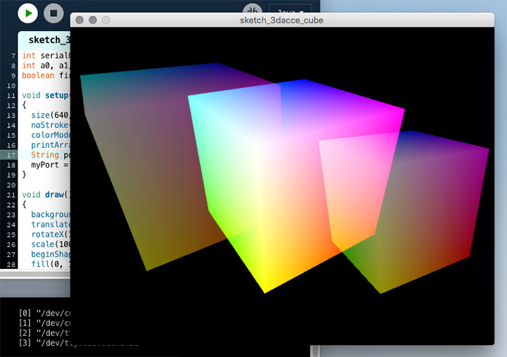
3. Running the Processing Sketch
Moving the Arduino’s acrylic board up, down, left, and right causes the cube to sway.
Rotating the Cube (Angle Values)
Calculate the tilt angle based on the acceleration values, send it to Processing, and use it as the rotation angle for the cube.
1. Preparing the Arduino Sketch
Create a new sketch, copy and paste the code below, and save the sketch.
// Cube rotation (angle values) (Arduino side)
// December 2017 nakayasu

int sensorValue[3];
int inByte; // Received data

void setup()
{
  for(int k=0; k < 3; k++) sensorValue[k] = 0;
  Serial.begin(9600); establishContact(); // To establish serial communication
}
void loop() {
  if (Serial.available() > 0) {
    inByte = Serial.read(); // Read from serial
    sensorValue[0] = analogRead(1); // A1 pin input - Z (pin 8 on KXM52-1050)
    delay(10);
    sensorValue[1] = analogRead(2); // A2 pin input - Y (pin 7 on KXM52-1050)
    delay(10);
    sensorValue[2] = analogRead(3); // A3 pin input - X (pin 6 on KXM52-1050)
    delay(10);

    // Scale the sensor values to the range of -1 to 1 to obtain the sinθ values
    float xAxisSinTheta = mapInFloat(sensorValue[2], 306, 716, -1, 1);
    float yAxisSinTheta = mapInFloat(sensorValue[1], 306, 716, -1, 1);
    // Limit the values to the range from -1 to 1
    xAxisSinTheta = constrain(xAxisSinTheta, -1, 1);
    yAxisSinTheta = constrain(yAxisSinTheta, -1, 1);
    // Convert the radians of the inverse sine to degrees
    int xAxisTilt = float(asin(xAxisSinTheta) * 180 / PI );
    int yAxisTilt = float(asin(yAxisSinTheta) * 180 / PI );
    // Send via serial
    Serial.write(xAxisTilt);
    Serial.write(yAxisTilt);
  }
}

void establishContact() { // Continue sending 'A' until serial communication is established
  while (Serial.available() <= 0) {
    Serial.print('A');
    delay(300);
  }
}

float mapInFloat(float x, float iMin, float iMax, float oMin, float oMax) {
  return (x - iMin) * (oMax - oMin) / (iMax - iMin) + oMin;
}
Download Sketch Data
Arduino_5-6_CubeByAngle_Arduino.zip (Currently unavailable)
② Uploading the Arduino Sketch
Compile and upload the sketch. Serial communication does not start immediately after the program is uploaded to the Arduino. Serial communication begins only after you launch Processing and the initial data exchange between the sender and receiver is complete.
3. Preparing the Processing sketch
Create a new sketch, copy and paste the code below, and then save the sketch.
// Cube rotation (angle value) (Processing side)
// December 2017 nakayasu

import processing.serial.*; // Load the serial library
Serial myPort;
int[] serialInArray = new int[2];
int serialCount = 0;
int xangle, yangle;
boolean firstContact = false;

void setup()
{
  size(640, 480, P3D);
  noStroke();
  colorMode(RGB, 1);
  printArray(Serial.list()); // Display serial devices on the console
  String portName = Serial.list()[3]; // Serial device number
  myPort = new Serial(this, portName, 9600);
}

void draw()
{
  background(0);
  translate(width/2, height/2, -30);
  rotateX(radians(-30+360*xangle/255));
  rotateZ(radians(-360*yangle/255));
  scale(100);
  beginShape(QUADS);
  fill(0, 1, 1); vertex(-1, 1, 1); fill(1, 1, 1); vertex( 1, 1, 1);
  fill(1, 0, 1); vertex( 1, -1, 1); fill(0, 0, 1); vertex(-1, -1, 1);

  fill(1, 1, 1); vertex( 1, 1, 1); fill(1, 1, 0); vertex( 1, 1, -1);
  fill(1, 0, 0); vertex( 1, -1, -1); fill(1, 0, 1); vertex( 1, -1, 1);

  fill(1, 1, 0); vertex( 1, 1, -1); fill(0, 1, 0); vertex(-1, 1, -1);
  fill(0, 0, 0); vertex(-1, -1, -1); fill(1, 0, 0); vertex( 1, -1, -1);

  fill(0, 1, 0); vertex(-1, 1, -1); fill(0, 1, 1); vertex(-1, 1, 1);
  fill(0, 0, 1); vertex(-1, -1, 1); fill(0, 0, 0); vertex(-1, -1, -1);

  fill(0, 1, 0); vertex(-1, 1, -1); fill(1, 1, 0); vertex( 1, 1, -1);
  fill(1, 1, 1); vertex( 1, 1, 1); fill(0, 1, 1); vertex(-1, 1, 1);

  fill(0, 0, 0); vertex(-1, -1, -1); fill(1, 0, 0); vertex(1, -1, -1);
  fill(1, 0, 1); vertex( 1, -1, 1); fill(0, 0, 1); vertex(-1, -1, 1);
  endShape();
}

void serialEvent(Serial myPort) {
  int inByte = myPort.read();
  if (firstContact == false) {
    if (inByte == 'A') {
      myPort.clear(); // clear the serial port buffer
      firstContact = true; // you've had first contact from the microcontroller
      myPort.write('A'); // ask for more
    }
  } else {
    // Add the latest byte from the serial port to array:
    serialInArray[serialCount] = inByte;
    serialCount++;
    if (serialCount > 1 ) {
      xangle = serialInArray[0];
      yangle = serialInArray[1];
      myPort.write('A'); // Send a capital A to request new sensor readings:
      serialCount = 0; // Reset serialCount:
    }
  }
}
Download Sketch Data
Arduino_5-6_CubeByAngle_Processing.zip (Currently unavailable)
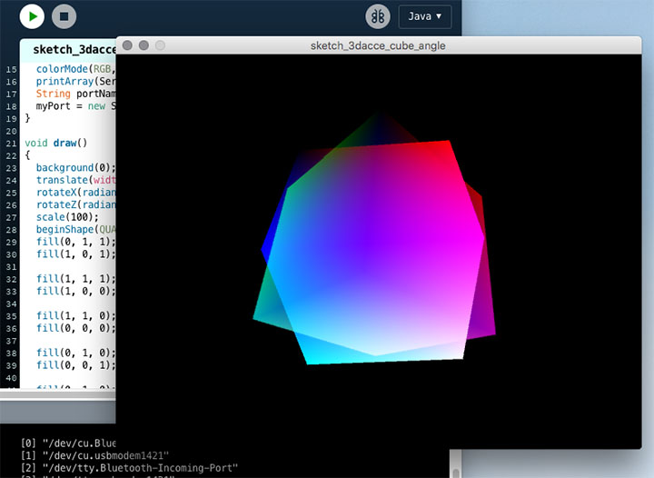
④Running the Processing Sketch
Tilting the Arduino’s acrylic board causes the cube to rotate.
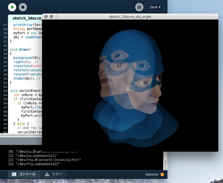
Rotating 3D Models
1. Preparing and Uploading the Arduino Sketch
Use the same Arduino sketch as in “6. Rotating the Cube (Angle Values).”
2. Preparing the Processing sketch
Create a blank sketch, copy and paste the code below, and then save the sketch.
// Rotating a 3D model (angle value) (Processing side)
// December 2017 nakayasu

import processing.serial.*; // Load the serial library
Serial myPort;
int[] serialInArray = new int[2];
int serialCount = 0;
int xangle, yangle;
boolean firstContact = false;
PShape obj;

void setup()
{
  size(640, 480, P3D);
  noStroke();
  colorMode(RGB);
  printArray(Serial.list()); // Display serial devices on the console
  String portName = Serial.list()[3]; // Serial device number
  myPort = new Serial(this, portName, 9600);
  obj = loadShape("captain_blender.obj"); // Load 3D object data
}

void draw()
{
  background(0);
  lights();  // Add lights
  translate(width/2, height/2-30, 100); // Adjust position
  rotateX(radians(175+360*xangle/255)); // Rotation angle
  rotateY(radians(-180+360*yangle/255)); // Rotation angle
  shape(obj); // Display 3D data
}

void serialEvent(Serial myPort) {
  int inByte = myPort.read();
  if (firstContact == false) {
    if (inByte == 'A') {
      myPort.clear(); // clear the serial port buffer
      firstContact = true; // you've had first contact from the microcontroller
      myPort.write('A'); // ask for more
    }
  } else {
    // Add the latest byte from the serial port to array:
    serialInArray[serialCount] = inByte;
    serialCount++;
    if (serialCount > 1 ) {
      xangle = serialInArray[0];
      yangle = serialInArray[1];
      myPort.write('A'); // Send a capital A to request new sensor readings:
      serialCount = 0; // Reset serialCount:
    }
  }
}
Download Sketch Data
Arduino_5-7_OBJByAngle_Processing.zip (Currently unavailable)
3. Preparing 3D Model Data
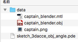
Open the Sketch menu > Open Sketch Folder.
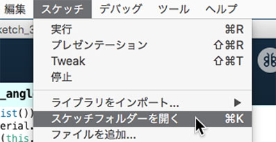
Create a “data” folder and place the following three files (captain_password.zip (currently unavailable), password required) inside it.
・captain_blender.mtl
・captain_blender.obj
・captain.png
④Running the Processing Sketch
Rotating the Arduino’s acrylic board causes the captain to rotate.