Live-Action VFX - Part 3
Updated: 2026-05
1. Goals and Production Methods
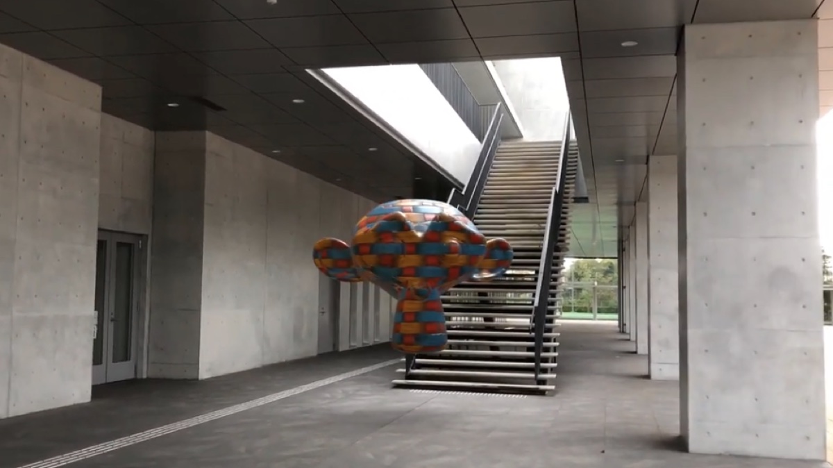
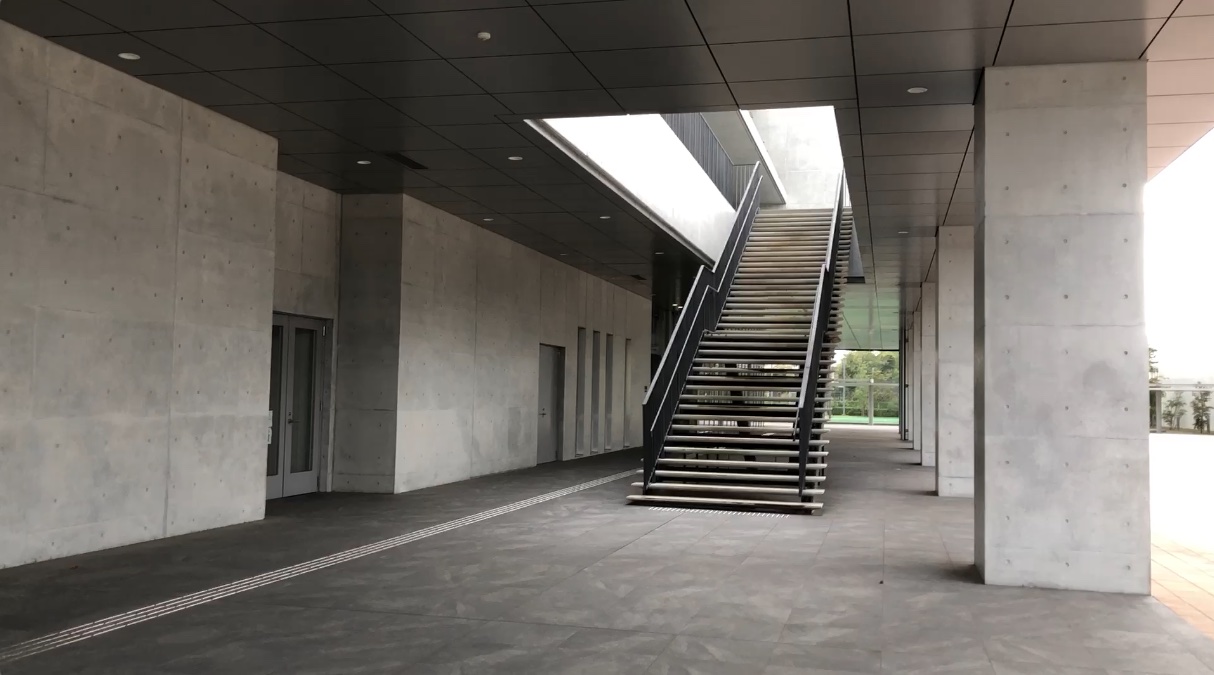
Make Monkey float in the footage taken in front of Building 6 on the Hino Campus.
- The main difference from Parts 1 and 2 is that the camera does not move; it simply shakes in place.
- Perform the analysis using the Tripod settings.
- Use Eevee and HDRI.
- Since the Floor settings are meaningless, you need to manually adjust the camera direction.
- Use Blenderkit materials.
- Reference: YouTube - Blender 3D Camera Tripod Tracking Beginner Tutorial.
(Reference: Research on Tripod Motion)
- Solve - Blender 4.2 Manual (Translated from the download, key points excerpted)
- Tripod Motion can be used for footage where the camera remains stationary and only rotates.
- Such footage cannot be tracked using the generic solver approach, as there is insufficient information to determine the actual spatial locations of the feature points.
- Therefore, this solver solves only the relative rotation of the camera and reprojects all feature points onto a sphere by setting the distance between the feature and the camera to be the same for all feature points.
- This is a special type of camera solver, and its behavior differs from that of standard solvers.
- In other words, using more tracks does not necessarily result in a more accurate solution. Typically, solvers of this type use 5–10 tracks per frame. (DeepL translation)
2. Preparation
2.1 Downloading Raw Video Data
Distributed via the kibaco announcement.
File name: hinoD_20240916.mp4
2.2 Launching Blender
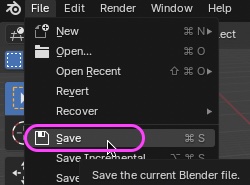
Launch Blender and delete the cube.
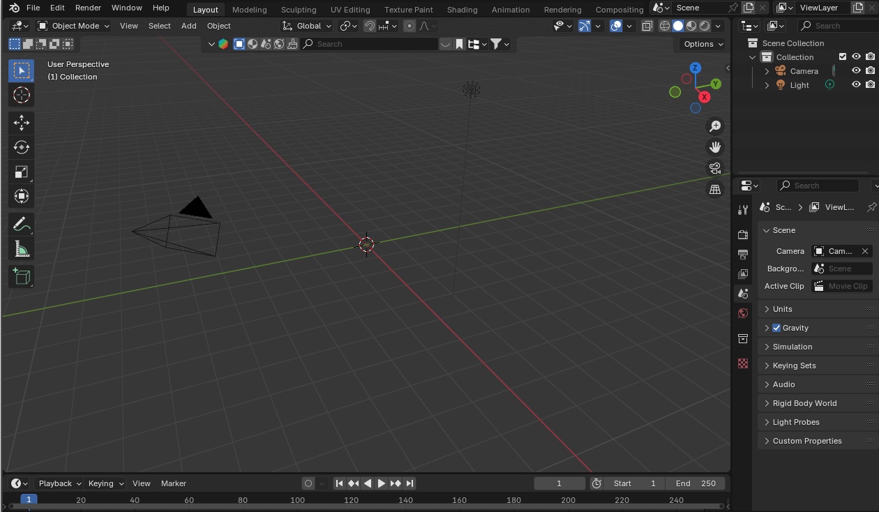
Save the project file to a location of your choice.
2.3 Displaying the Motion Tracking Workscape
Click the “+” (Add Workspace) button on the far right of the workspace.
Add VFX > Motion Tracking from the menu.
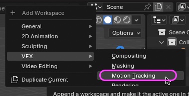
The Motion Tracking Workspace appears.
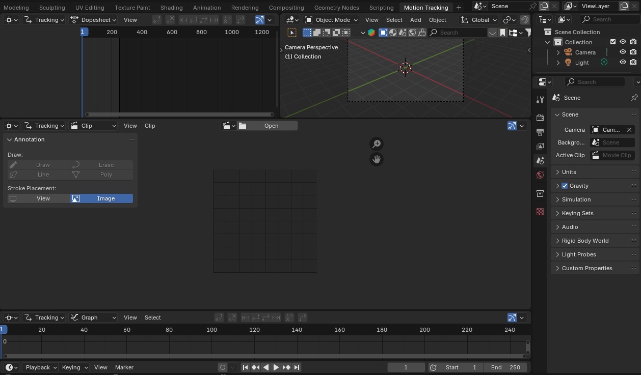
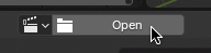
2.4 Importing Footage
Click “Open” in the center of the Movie Clip Editor (middle panel) to load hinoA_20240917.mp4.
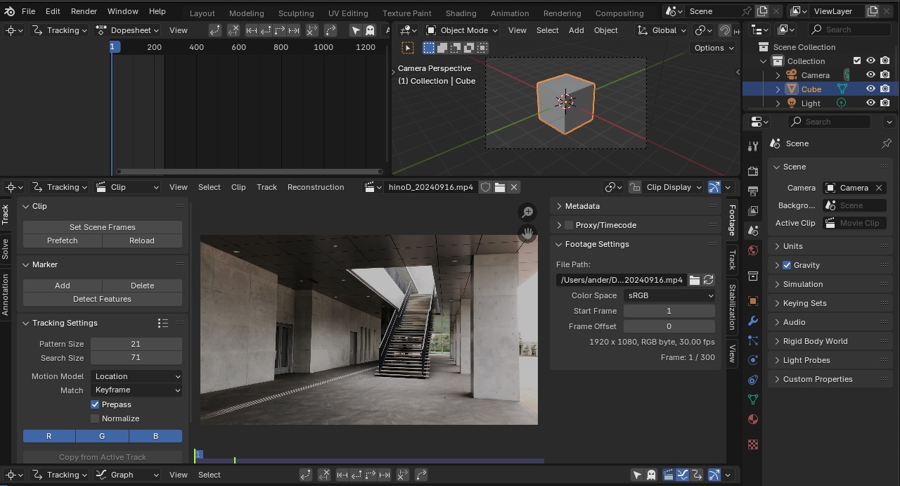
Follow these steps to set up the project:
- Toolbar > Track > Clip
- OUT Point: 150 (halfway through the 300-frame video clip)
- Click “Prefetch”
- Output Properties
- Set the Framerate, Resolution X, and Resolution Y to match the values in the Footage Settings section of the sidebar
3. Adding Markers and Tracking (Manual)
Add and track markers in the same way as described in “7. Adding and Tracking Markers (Manual)” in Part 1.
- Leave the Tracking Settings at their default values.
- Move the time indicator to a point near the center between the IN and OUT points.
- Add a marker by pressing Cmd + left-click.
- Display the Marker Display information as needed.
- Perform Forward Tracking and Backward Tracking.
- Use the Lock function to verify as needed.
- Number of markers: Approximately 5–10
- Having too many does not seem to be helpful.
- With the Tripod setting, Solve will not return an error even with just one marker; however, with only one marker, the camera itself will spin in circles, so you need at least two markers.
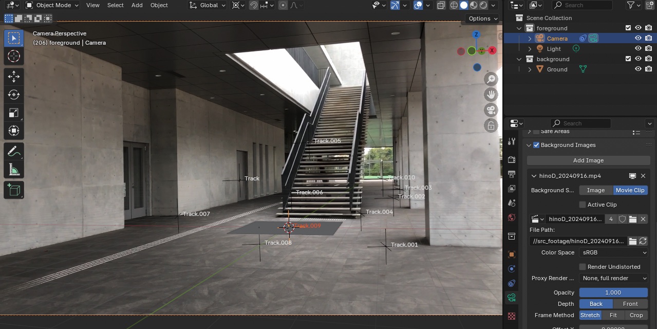
The image below is worth about 10 points.
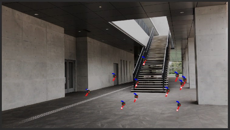
As shown in the figure below, add a marker designed for use with Origin during post-processing.
4. Solve (Analysis of Camera Movement)
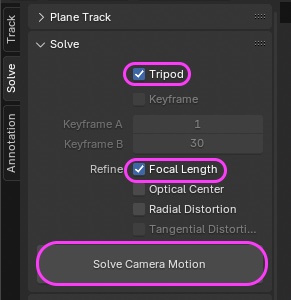
Check the boxes below and click “Solve Camera Motion.”
-
Tripod
-
Focal Length *Specify the Optical Center (Origin) manually.
-
When using a tripod, the analysis results will consist solely of the Rotate element, and the Location information will be ignored.
-
Strictly speaking, handheld cameras differ from tripods in that the Location may shift slightly, but we don’t enforce this rule too strictly.
-
If you want to be precise, you should use a tripod; even when shooting handheld, it’s best to maintain the camera’s position in the air while filming.
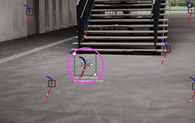
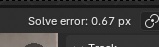
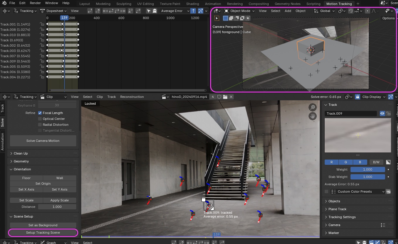
Check the “Solve error” value. If it is too high, delete the markers causing the error and try solving again.
If everything looks good, click “Setup Tracking Scene.”
The camera’s movement (rotation) will be reflected in the Viewport in the upper-right panel.
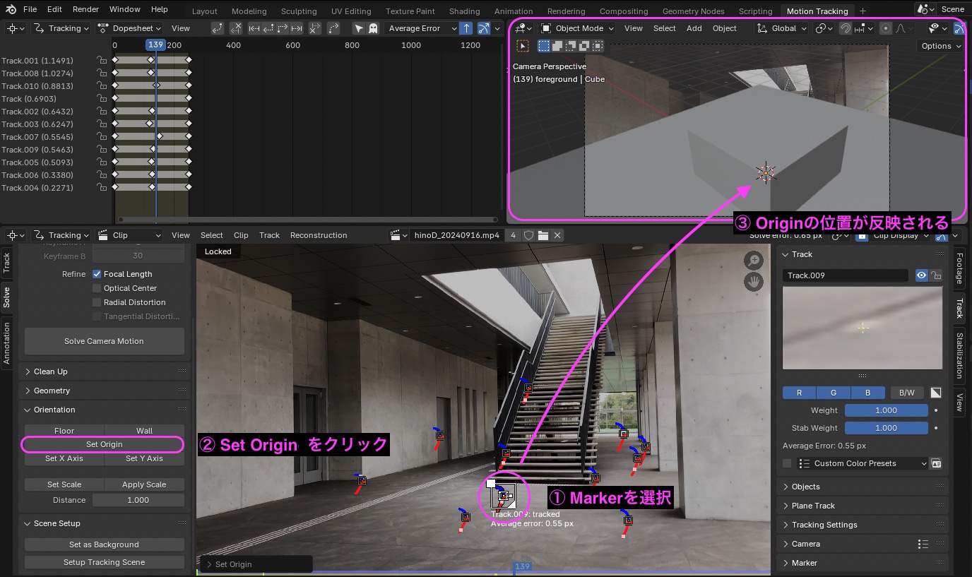
Select the marker shown below and click “Set Origin.”
The origin’s position will be displayed in the viewport at the top right.
5. Applying Analysis Results to the Scene
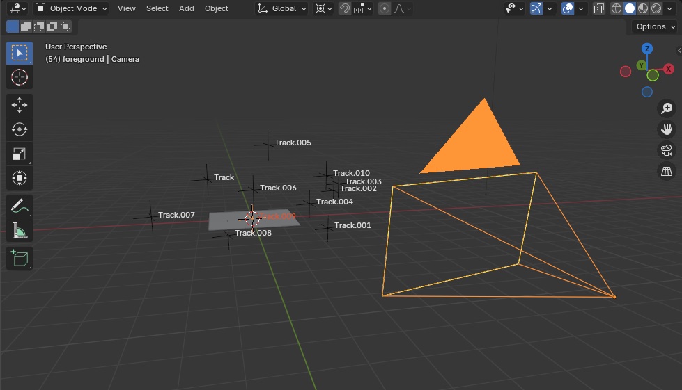
5.1 Reviewing the Camera Analysis Results (Motion)
- Switch to the Layout Workspace
- Display the following in Viewport Overlays:
- Motion Tracking
- Camera Path
- Marker Names
Play the video and verify that the camera position remains unchanged (no change in “Location”) and that it moves only via rotation.
5.2 Adjusting the Camera’s Orientation
Do not use the Floor settings; align manually This requires trial and error and practice
-
Delete the Cube
-
Scale down the Ground (Plane)
-
Increase the grid density in the Viewport
-
Reduce the Scale of the Guides in the Viewport Overlay to make the grid finer
-
Change the Transport Pivot Point to the 3D Cursor.
-
Select the camera.
Adjust the following settings to manually align the composition.
-
Align the tilt
- R, X
- R, Y
-
Align the orientation
- R, Z
-
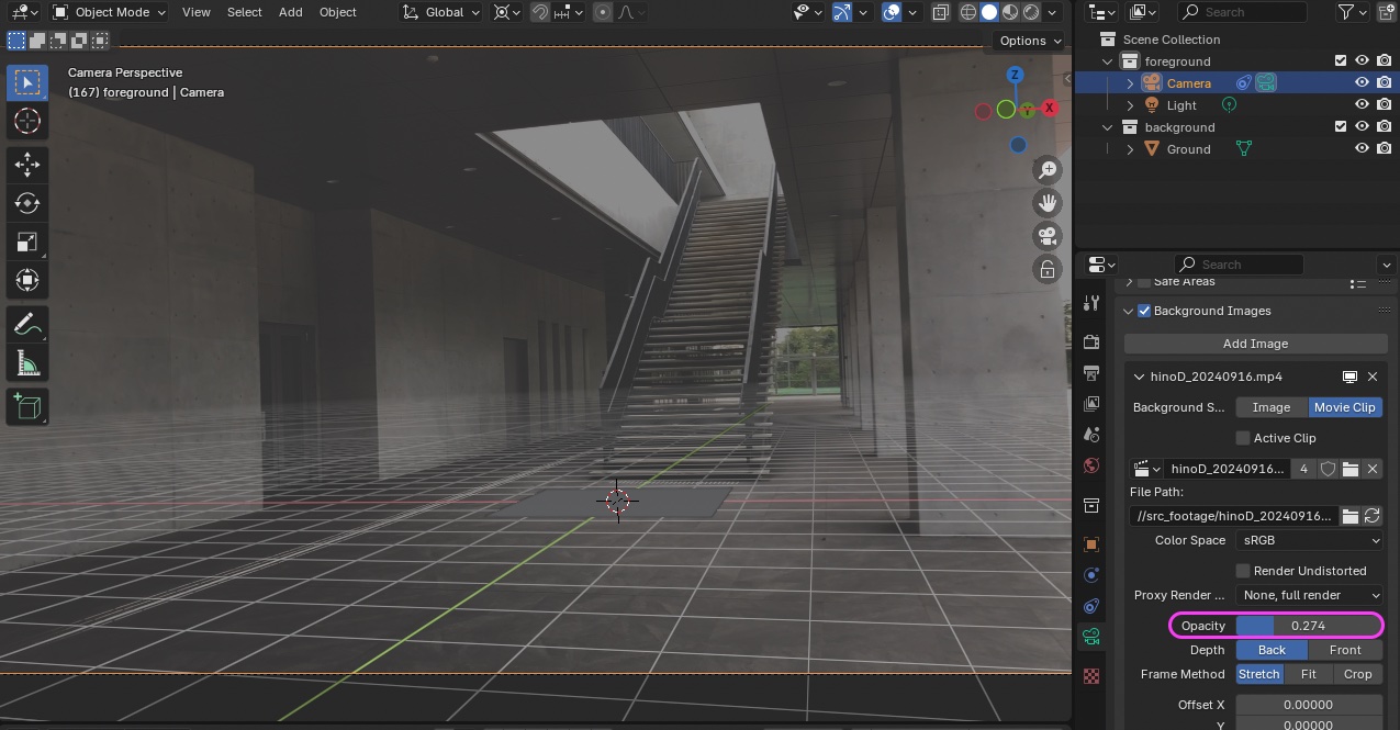
If necessary, lowering the opacity of the camera’s background will make the grid easier to see.
-
Depending on the camera, distortion may occur around the edges of the lens, so instead of leveling the shot at the edges of the frame, align the horizon near the center. In this case, it’s easier to level the shot by aligning it with the bottom of the stairs.
Note: As you experiment, you should start to see a clear direction for refining your approach.
- Set the Transport Pivot Point back to the Median Point.
- Reset the Viewport grid opacity.
- Change the Camera Background Opacity to 1.0.
(Nakayasu’s Note) hino_BLD_w6.blend
6. Creating a Scene
6.1 Monkey
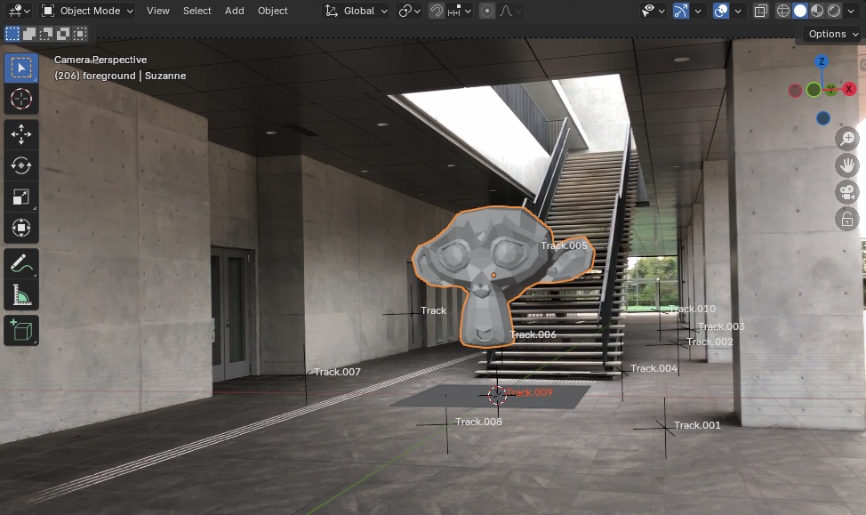
Add a “Mesh > Monkey” object and move it slightly upward using the G and Z keys.
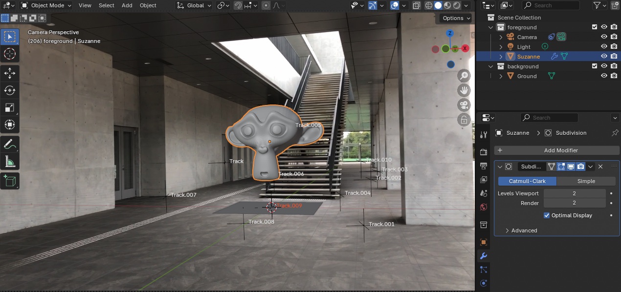
- Add a Subdivision Surface Modifier (Levels Viewport: 2) to Monkey
- Change to Shade Smooth.
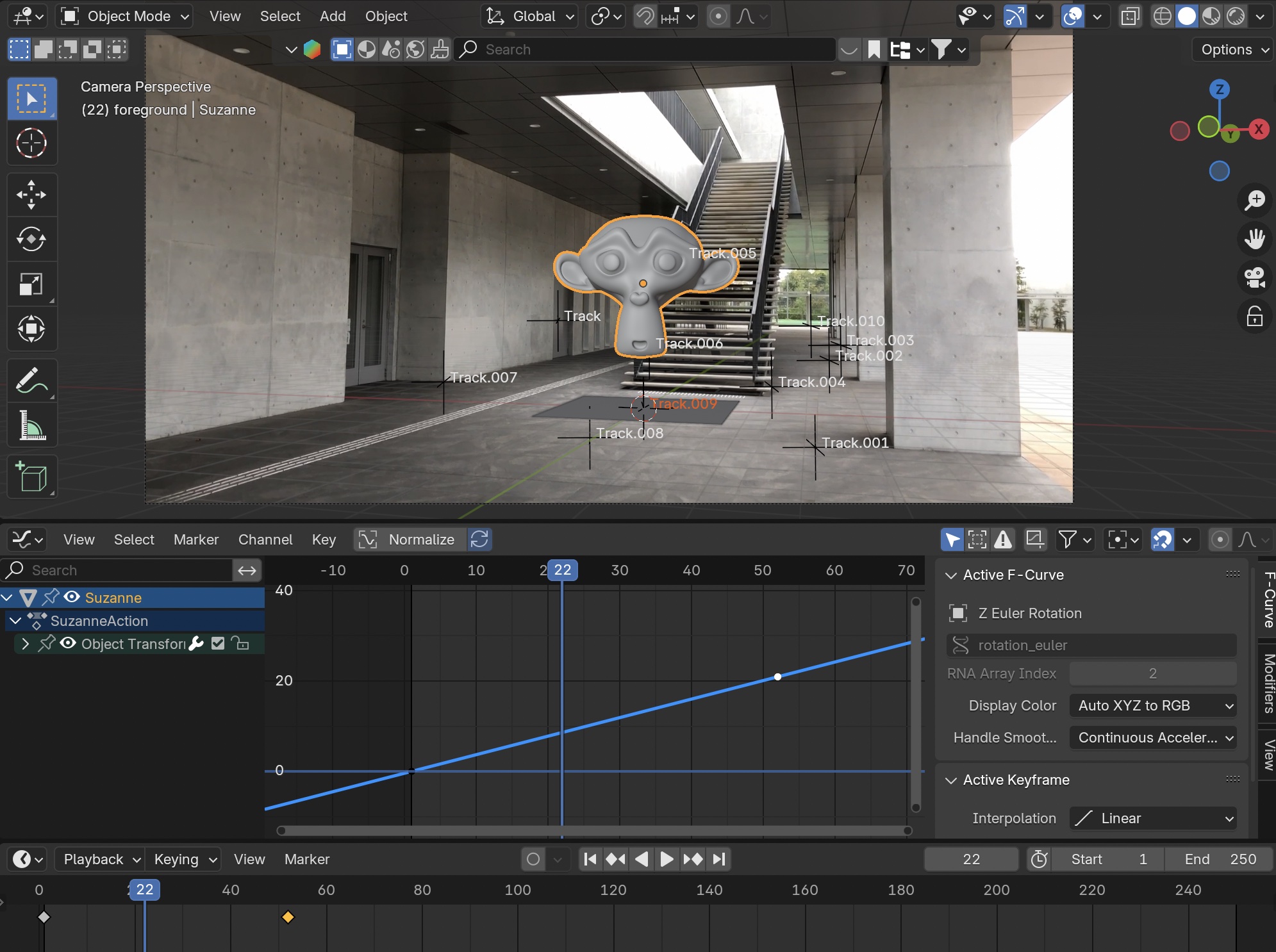
6.2 Rotation Animation
Set up the rotation animation for Monkey using “Method 1: Keyframe Method” in the rotation animation section.
(Nakayasu Note) hino_BLD_keyframeRotation_w10.blend
7. Understanding HDRI and Shadows in the Eevee Environment (Explanation Only)
Up until version 4.1, Eevee did not generate shadows from HDRI images. As a result, users had to add a “Light” to create shadows. Starting with version 4.2, Eevee can now cast shadows from HDRI images. Ray tracing capabilities, which enable features such as shading and reflections, have also been added, resulting in an update that brings Eevee closer to Cycles. Eevee versions 4.2 and later are referred to as Eevee 2.0 or Eevee Next.
References)
- Blender 4.2 - Eevee Shadows Without Sun in One Click!
- Eevee Features Ray Tracing in Blender 4.2!
- Will Eevee 2.0 Replace Cycles? | Blender 4.2
- Blender 4.2 EEVEE NEXT: Basic Lighting Settings | Osamu Kitani
8. HDRI Settings
This exercise does not use Cycles rendering
8.1 Preparation
-
Change OUT to 150 (because it’s long)
-
Viewport Shading: Rendered (Render Engine is Eevee)
-
Use the Outline filter to display Holdout and Indirect Only
-
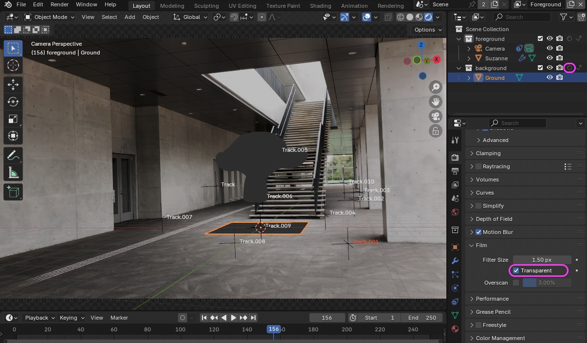
Turn off Holdout in the Background Collection
-
Delete existing lights
-
Check the “Transparent” box in Render Properties > Film.
-
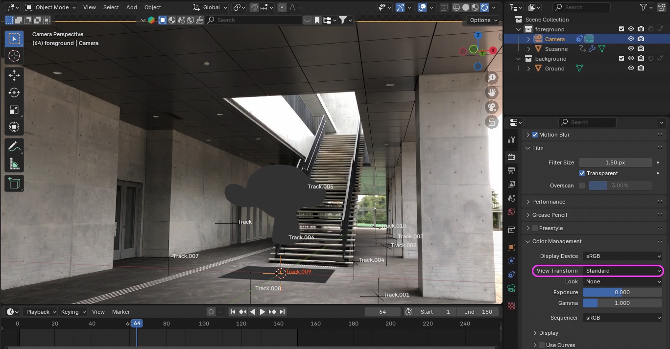
Issue with background video contrast Not covered in Part 2 exercises
- Go to Render Properties > Color Management > View Transform and change the setting from AgX to Standard.
- You can adjust the image appearance to your liking. This method is intended only for cases where you want to render the footage exactly as it is.
-
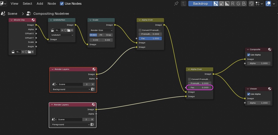
Set the Fac parameter of the second Alpha Over node in the Composite to zero. This is not covered in the Part 2 exercise.
8.2 Downloading HDRI Files
Find the most suitable HDR image from Blenderkit, Polyhaven, or similar sites. For this tutorial, download “hangar_interior_4k.exr” from the following link: https://polyhaven.com/a/hangar_interior https://scrapbox.io/files/66ea722547093d001dbdf52f.webp
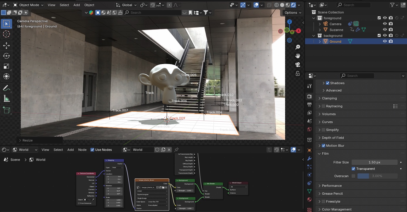
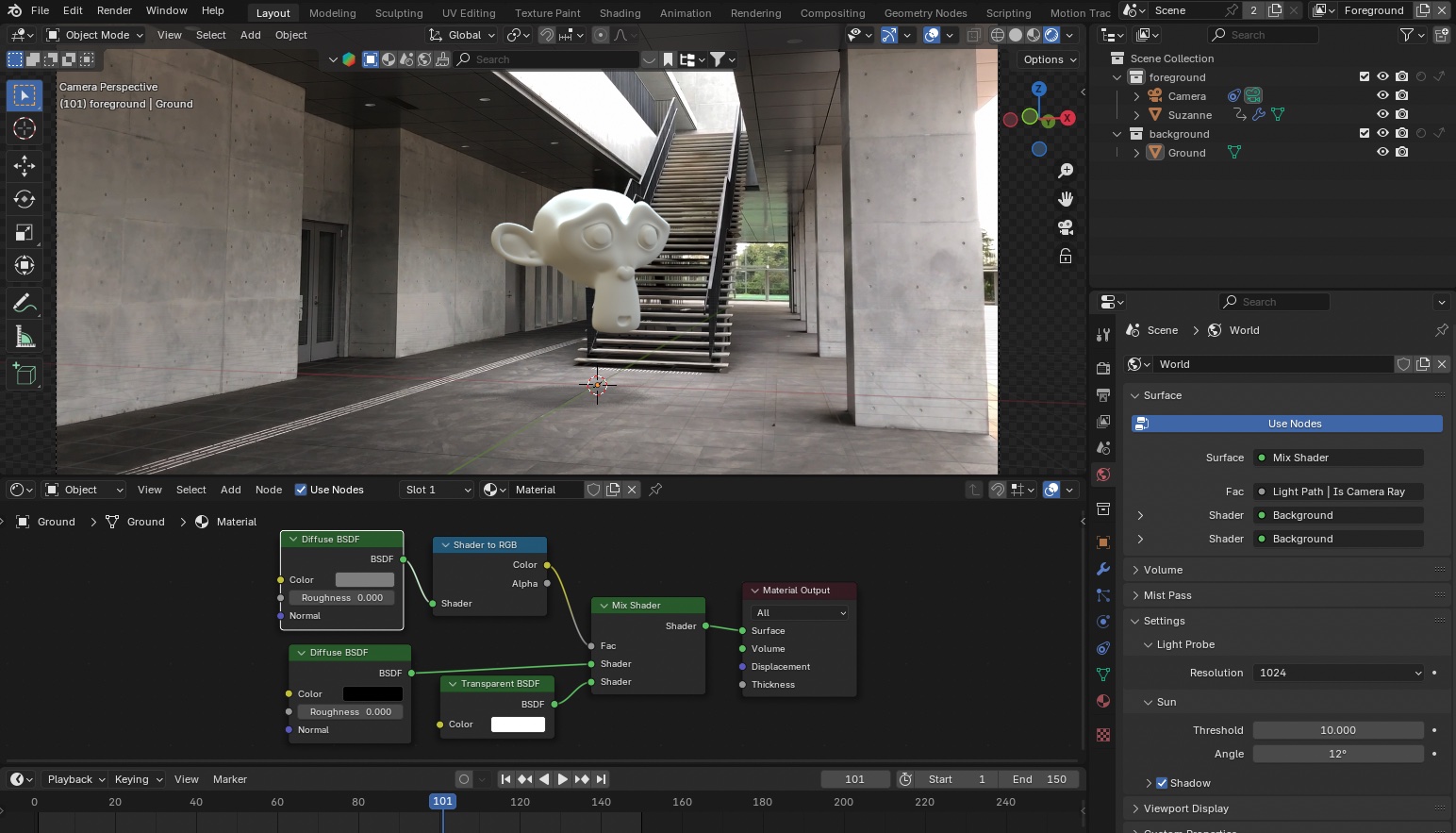
8.3 World Node
Switch to “World” in the Shader Editor.
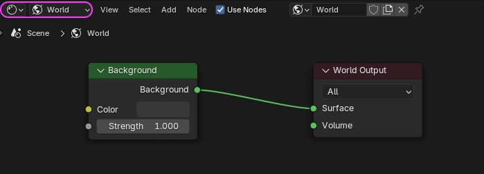
Assemble the following nodes and load the downloaded hangar_interior_4k.exr file.
- Texture Coordinate
- Mapping
- Environment Texture
- The appearance can vary significantly depending on the Color Space and Alpha settings
- Background (two in total, including the existing one)
- Light Path
- Mix Shader
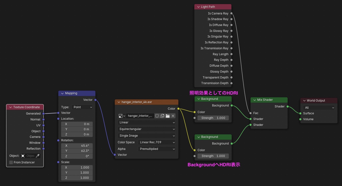
The image is overexposed at this point, but that’s okay.
 (Nakayasu Memo) hino_BLD_keyframeRotation_w12.blend
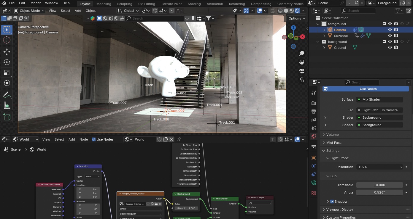
- Turn off “Transparent” under Render Properties > Film to check the effects of the HDRI image and Mokey’s shadows.
- You can still view the HDRI image even when rotating the viewport.
- Increase the size of the ground if necessary.
- At this point, changing the “Threshold” under World Properties > Settings > Sun from 10 to around 2 will make the shadows darker, making them easier to see.
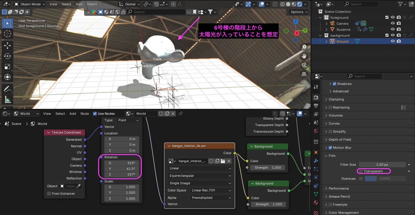
- Rotate the Mapping node to adjust the direction of the shadows.
- In the figure below, set the values approximately as follows to create the impression that light is entering from the stairs of Building 6.
- Rotation X: 330
- Rotation Y: 42
- Rotation Z: 260
 (Nakayasu Memo) hino_BLD_keyframeRotation_w13.blend
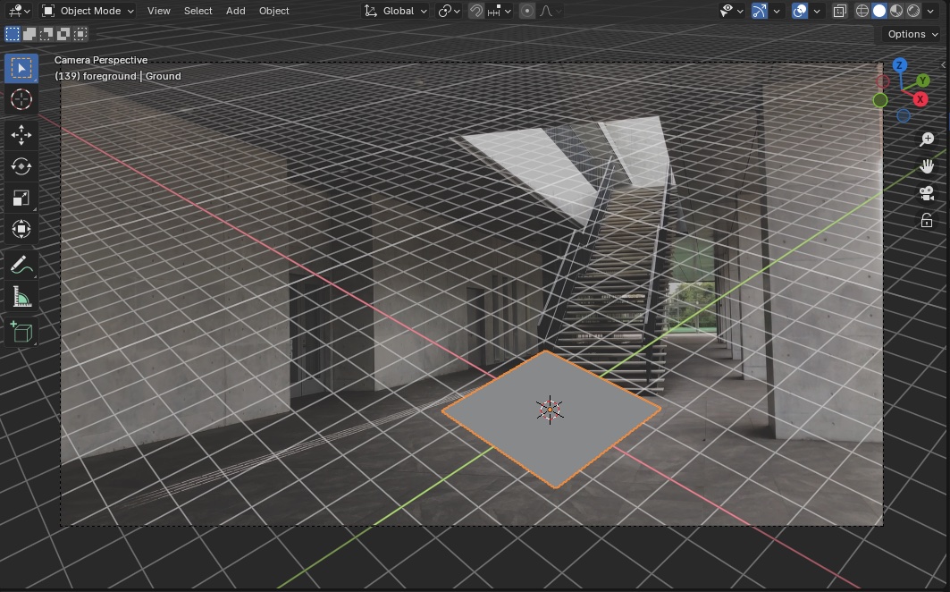
- Return the view to Camera View.
- Go to Render Properties > Film > Transparent and turn it back on.
- If the Ground is too large, resize it to approximately the dimensions shown in the figure below.
 (Nakayasu Memo) hino_BLD_keyframeRotation_w14.blend
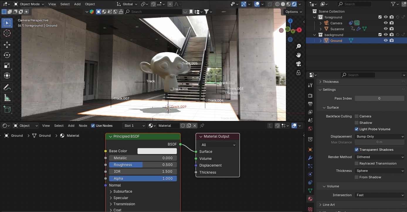
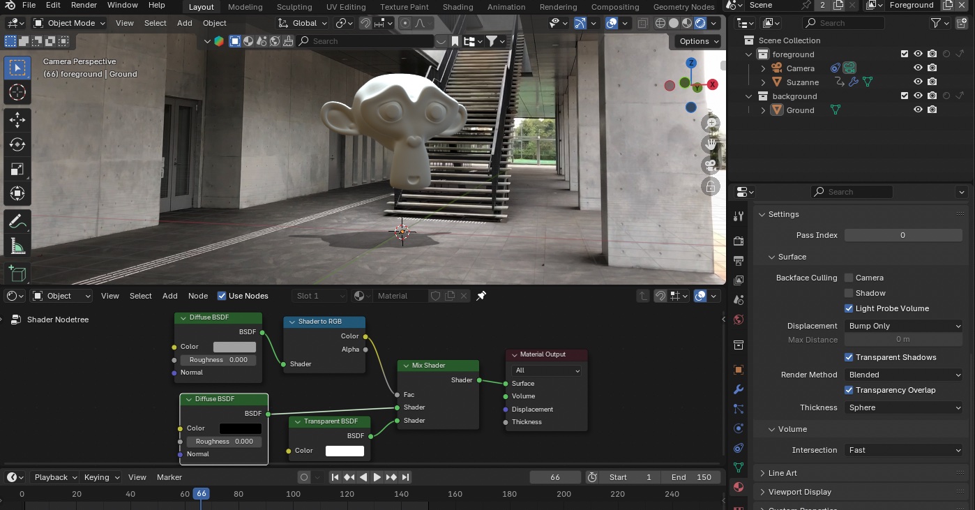
9. Ground Transparency
9.1 Creating Material Nodes
-
Select the Ground object
-
In the Shader Editor, switch the Shader Type to Object.
-
Create a material by clicking NEW in the center of the Shader Editor menu.
-
If they’re in the way, hide the Motion Tracking section in Viewport Overlays.
-
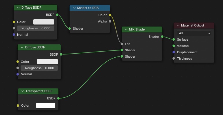
Remove the Principled BSDF Create the following nodes and connect them as shown in the figure below.
-
Diffuse BSDF (2)
-
Transparent BSDF *Do not confuse this with Translucent BSDF
-
Shader to RGB
-
Mix Shader
Go to Material Properties > Settings > Render Method and change the setting from “Dithered” to “Blended.”
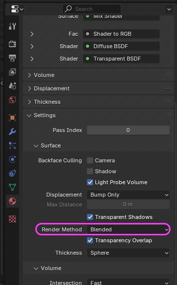
For now, only change the green sections listed below. You will need to adjust these again later after adjusting the light.
- First Diffuse BSDF: Shadow intensity (also affected by light intensity; uses HDRI only here)
- Hue: 0.0
- Sat: 0.0
- Val: 0.4
- Second Diffuse BSDF: Affects shadow intensity and color
- Hue: 0.0
- Sat: 0.0
- Val: 0.0
- Transparent BSDF: Transparency? (Light intensity also affects this; only HDRI is used here)
- Hue: 0.0
- Sat: 0.0
- Val: 1.0
 (Nakayasu Memo) hino_BLD_keyframeRotation_w15.blend
10. Fine-Tuning
10.1 Policy
- The next question is: how dark do you want Monkey’s “Shade” and Ground’s “Shadow” to be?
- To make Monkey stand out, should it be slightly brighter, or would it be better to make it darker?
- Some people handle this in Composite, but I’ll try adjusting it in the Eevee preview as much as possible.
10.2 Preparatory Settings
- Check “Raytracing” under Render Properties
- Check “Shadow” under World Properties > Settings (default setting)
10.3 Various Adjustments
- World Properties > Settings > Sun > Threshold: 10 (optional) – Shadow intensity; increasing this value makes the shadows lighter
- You can adjust the Threshold between 1 and 10 to suit your preference
- World Properties > Settings > Sun > Angle: 12 – Degree of shadow blur
- Shader Editor > Object (Ground) > Value of the Diffuse BSDF node above: 0.25 (Shadow intensity)
- Shader Editor > World > Adjust the Strength of the Background node above: 1.0
- This will brighten the shadowed areas slightly, but it’s probably better to adjust other parameters instead of changing this one.
(Notes on visual effects adjustments)
- In the lower video, the monkey is recognizable from the start.
- In contrast, in the shadow effect in #9, the monkey is difficult to make out at first and becomes recognizable after a brief delay.
- Which approach is better depends on the visual effect and the speed of the movement.
 (Notes by Nakayasu) hino_BLD_keyframeRotation_w16.blend
Here is a video rendering of what we’ve done so far.
11. Adding Materials to Monkey
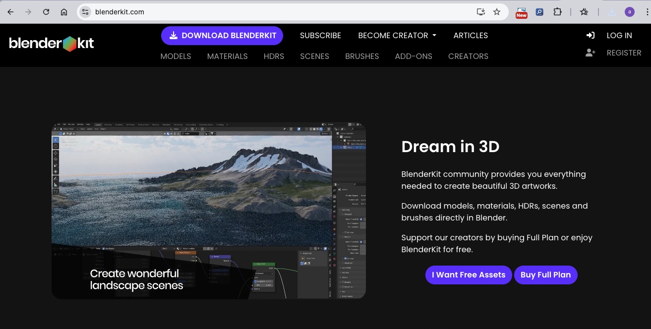
11.1 Installing BlenderKit
https://www.blenderkit.com/get-blenderkit/
Download the blenderkit-v*.zip file from the website above.
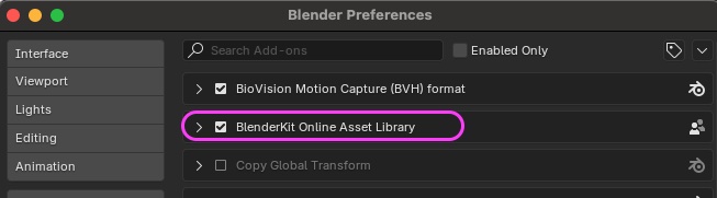
In Blender Preferences > Add-ons, click the ▼ button in the upper-right corner, select “Install from Disk,” and load blenderkit-v*.zip.
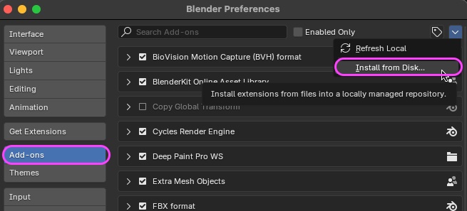
Installed.
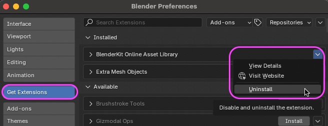
To uninstall, go to “Get Extensions.”
11.2 Assigning Materials in BlenderKit
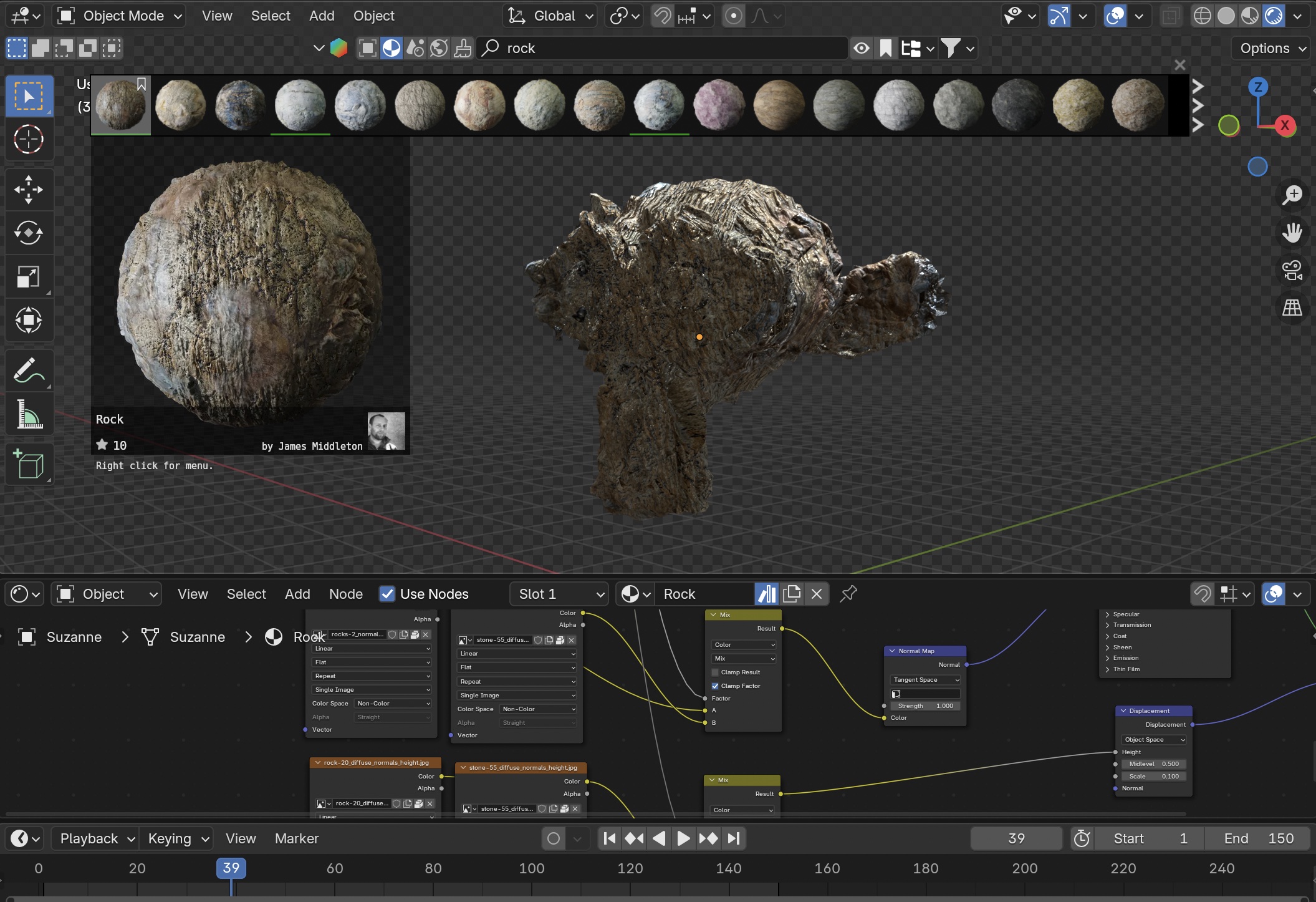
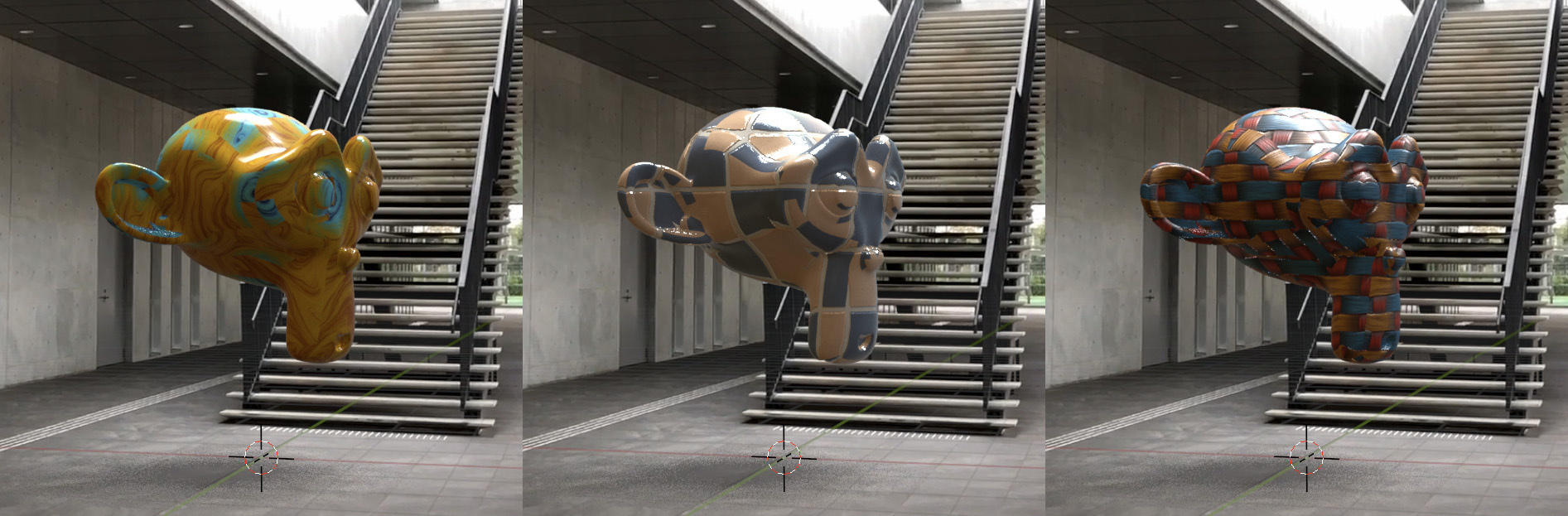
In BlenderKit, click the “Find Material” icon, search for “rock,” for example, and then drag and drop it onto “Monkey” to assign it, as shown in the figure below.
-
You can adjust the rough texture of the rock using the “Scale” parameter in the Displacement node.
-
World Properties > Settings > Sun > Change Threshold to 2. For rocks, is a darker shade better?
-
Shader Editor > Object (Ground) > Increase the value of the Diffuse BSDF above. Since darker shades make shadows darker too, should I make it a little lighter?
-
World Properties > Settings > Sun > Increase Angle to around 30.
- The image below shows a value of about 12, but it looks like it would be better to blur it.
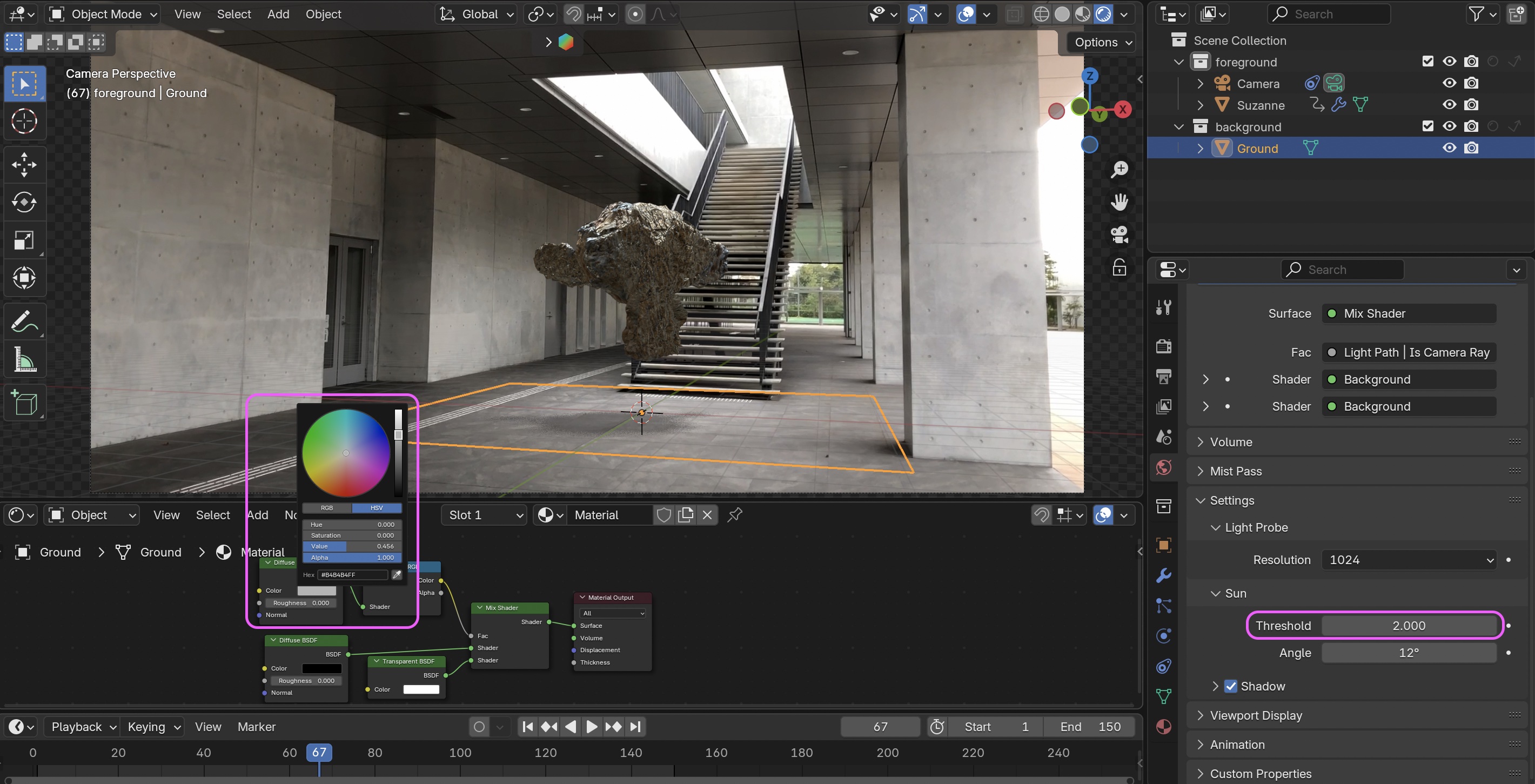
- The image below shows a value of about 12, but it looks like it would be better to blur it.
Let’s find the materials you like.
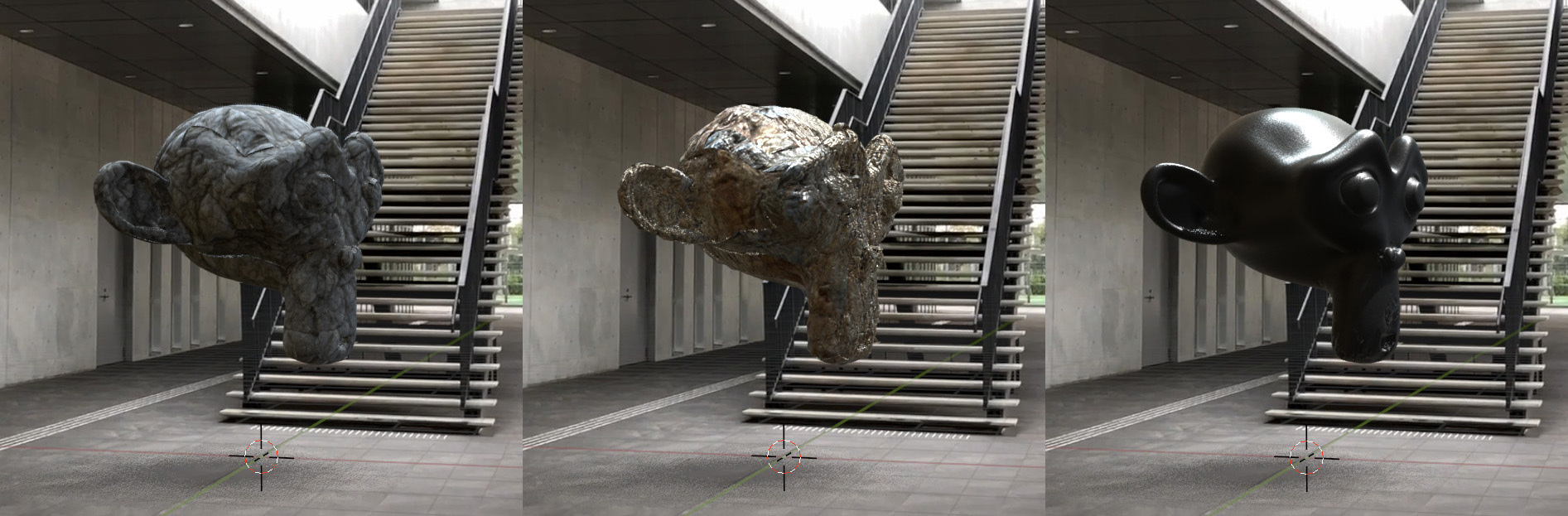
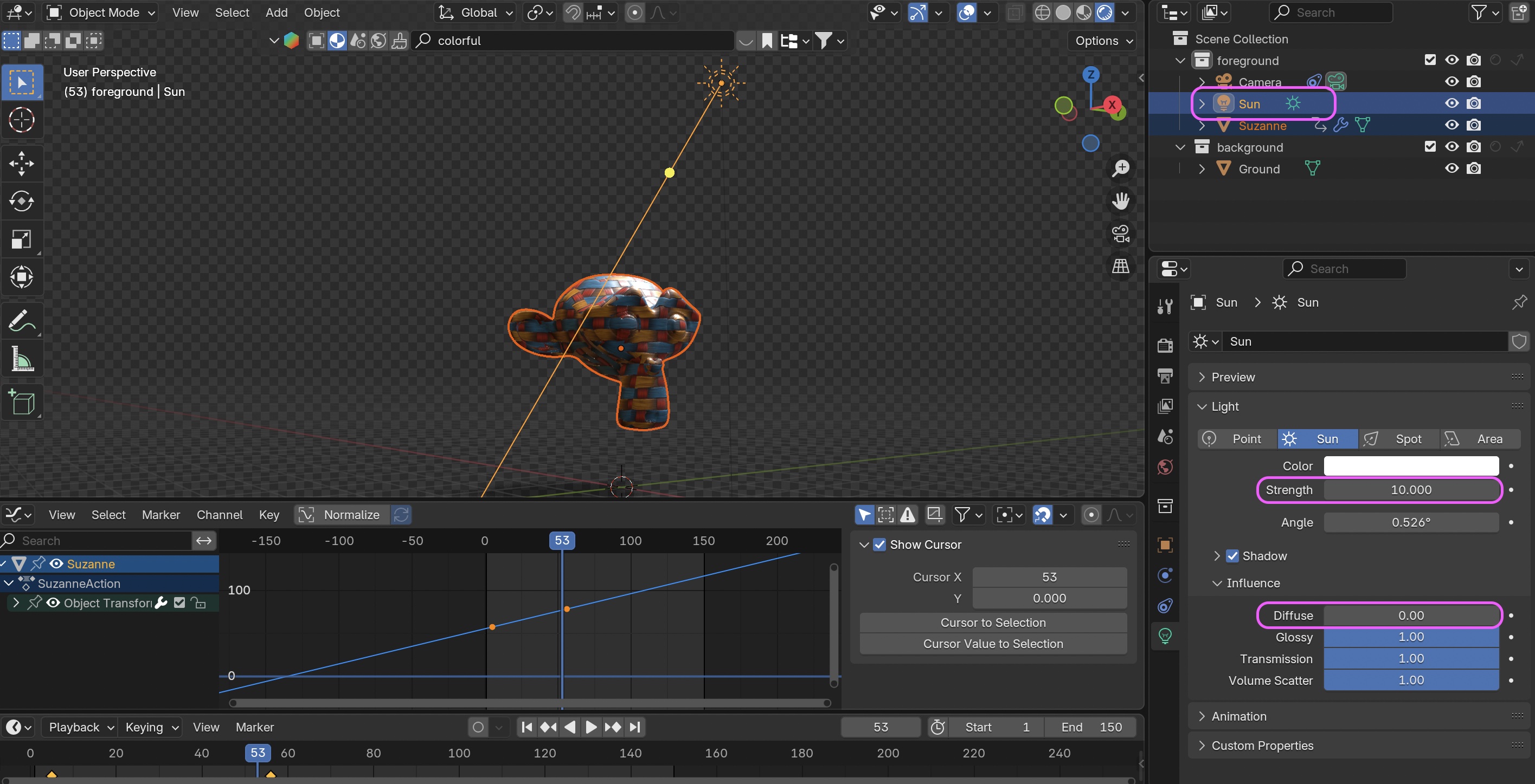
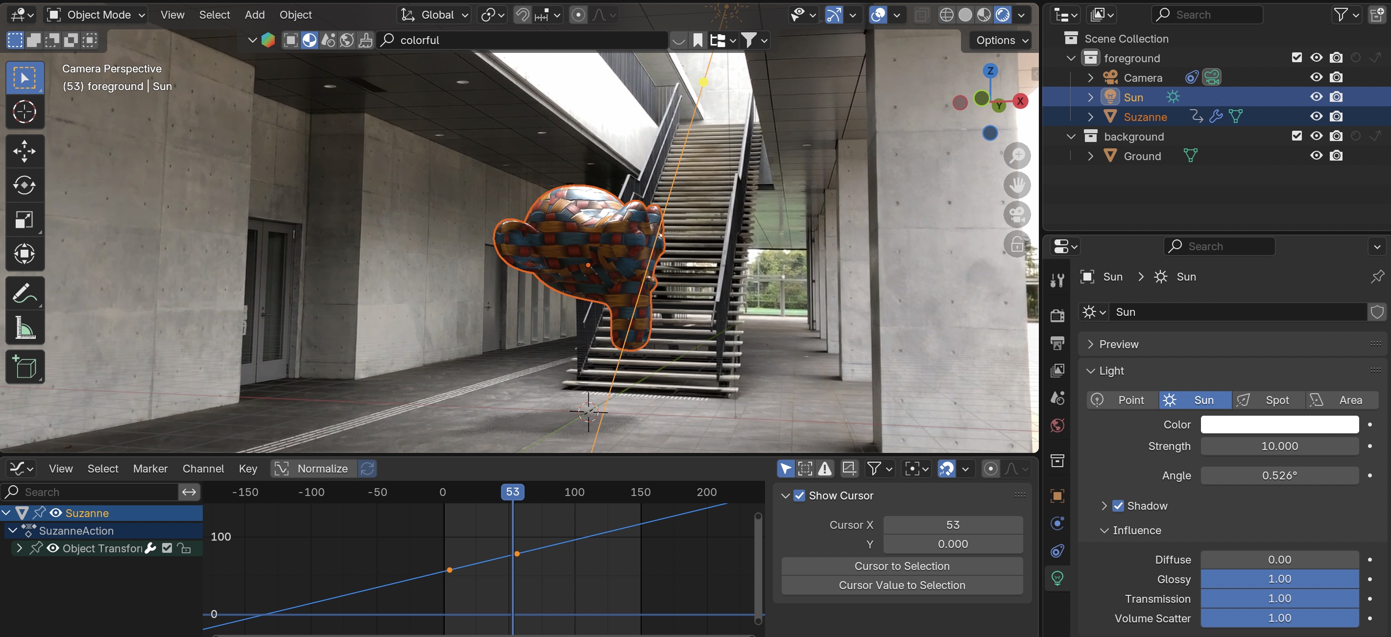
If the material is too dark, the texture details may appear to shift upward, so in some cases, you can add Sun Light to make the texture of the Monkey stand out more. Since Sun Light also affects shadows, you can eliminate its effect on shadows by setting the “Influence” for “Diffuse” to zero.
12. Video Rendering
It takes more than 30 minutes to render all frames.
Note: Since the clip was long, I set the OUT point to frame 150.
Configure the following settings, then select Render > Render Animation.
- Render Properties
- Resolution X: 1280 px
- Resolution Y: 720 px
- Frame Rate: 30 fps *Note: If you select the HDTV720p preset, the frame rate will be 24 fps
- Output
- Location: Any location/filename
- File Format: FFmpeg Video
- Encoding > Container: MPEG-4
- Video > Video Codec: H.264
- In some cases, it might actually look better if you don’t use Motion Blue or Raytracing.
- I didn’t include any people in this video, but I think it would be more interesting if I did. If you use a mask, you could even have the monkey walk right past the camera.
-
- By applying the techniques used here and the reference videos above, you can achieve effects similar to those seen at around 1:29, 2:19, and 2:43
-
YouTube - bonobos “THANK YOU FOR THE MUSIC”
- A music video from 20 years ago that was groundbreaking for its time