Arduino + LED
Updated: 2026-05

This article was written before 2020. It is kept here as an archive — the content is outdated and some links may no longer work.
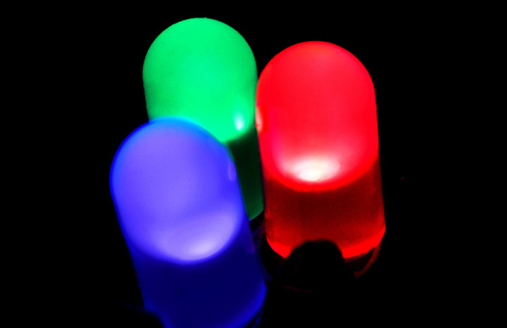
What Is an LED?
A light-emitting diode (LED) is a type of diode and a semiconductor device that emits light when a forward voltage is applied. (Wikipedia) With the invention of the blue LED in the 1990s, it became possible to reproduce full-color images, leading to its widespread use in video and lighting equipment.
Electronic Components Used
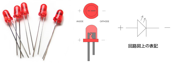
LED (Light-Emitting Diode) with Polarity
A semiconductor device that emits light when a forward voltage is applied (Wikipedia: Light-Emitting Diode).
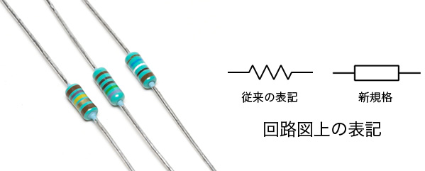
1/4W 10kΩ Resistor (Brown-Black-Orange-Gold), 1/4W 470Ω Resistor (Yellow-Violet-Brown-Gold), Non-polarized
Electronic components used for current limiting and voltage division. Formally known as resistors. Small resistors use color codes consisting of color bands to indicate resistance values and tolerance. The codes consist of 4 to 6 bands, which are read in order starting from the band closest to the end of the resistor. (Wiki: Resistor)
The color codes for the resistors used in this experiment are read as follows.
・Brown-Black-Orange: 1·0·3 = 10 × 10³ = 10,000 Ω = 10 kΩ; Gold: ±5%
・Yellow-Purple-Brown: 4·7·1 = 56 × 10¹ = 560 Ω; Tolerance: ±5%
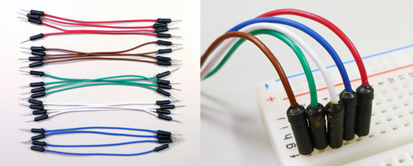
Jumper Cables (10 cm; 5 red or orange, 5 black or brown, 3 green, 1 white, 1 blue)
Cables for connecting components on a breadboard. Please note that the colors and quantities shown here differ from those in the photo.
How to Use a Breadboard
Unlike soldering on a circuit board, a breadboard allows you to connect components simply by inserting their leads. Because it can be reused repeatedly, it is commonly used for prototyping.
When inserting the component, you don’t need to push it all the way in, but if it’s inserted too shallowly, it may come loose, so insert it just far enough. If necessary, use needle-nose pliers to bend the leads, or trim them if they’re too long.
(Reference) Breadboard Master (Akizuki Denshi Tsushou)
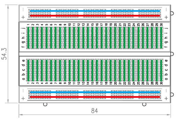
The figure below shows the EIC-801 we will be using and its internal wiring diagram.
Mounting the LED and Resistor
Components
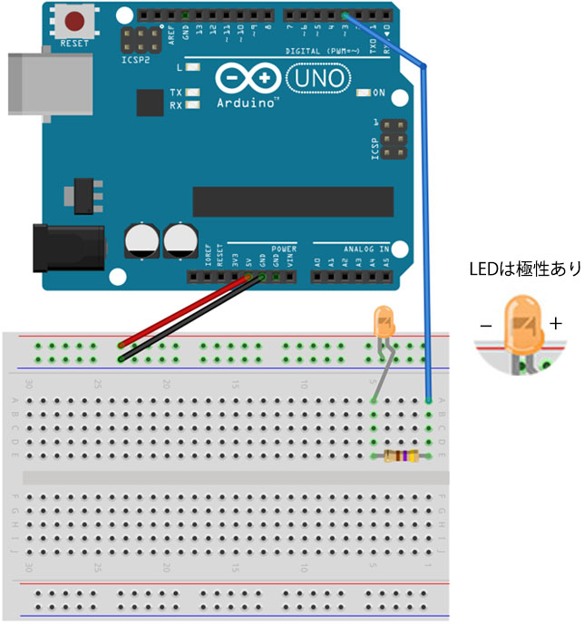
・LED (color varies by package) 1
・Resistor: 1/4W 470Ω (yellow, purple, brown, gold) – 1 piece
・Jumper wires: 1 red, 1 black, 1 blue
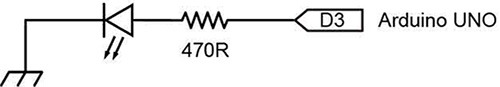
Circuit Diagram
Connect a resistor and an LED to digital output pin D3.
Implementation Diagram
Blinking LED
1. Sample Sketch
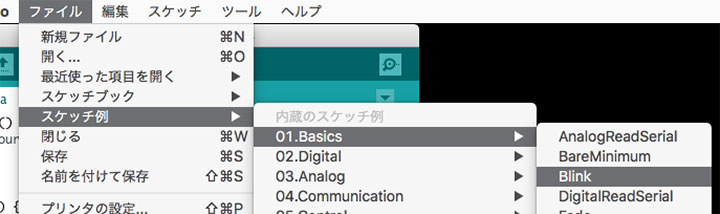
Open File Menu > Sample Sketches > 01.Basics > Blink.
2. Modifying the Sketch
Change all instances of LED_BUILTIN in the sketch to 3.
// The setup function runs once when you press the reset button or power on the board.
void setup() {
  // Initialize digital pin LED_BUILTIN as an output.
  pinMode(3, OUTPUT); // Set the pin as an output
}

// The loop function runs continuously indefinitely
void loop() {
  digitalWrite(3, HIGH);   // Turn the LED on (HIGH is the voltage level)
  delay(1000);                       // wait for a second (1000 ms)
  digitalWrite(3, LOW);    // turn the LED off by setting the voltage to LOW
  delay(1000);                       // wait for a second (1000 ms)
}
3. Verify Operation
Compile and upload the code, then verify that the LED is blinking.
Fade
1. Sample Sketch
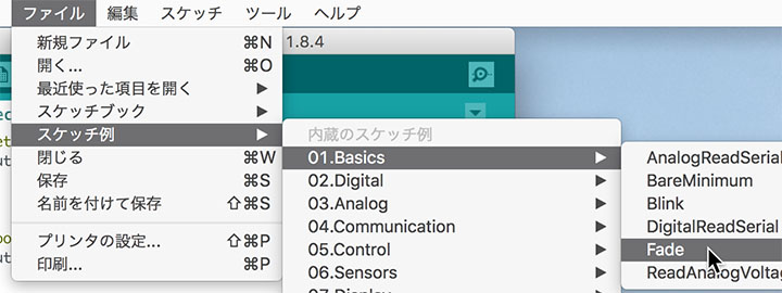
Open File Menu > Sample Sketches > 01.Basics > Fade.
2. Modifying the Sketch
Change the LED pin number to 3.
int led = 3; // the PWM pin the LED is connected to
*Note: The Arduino UNO R3’s built-in LED does not support PWM, so it will still blink even if you set it to pin 13. For more details, click here.
3. Verify Operation
Compile and upload the code, then verify that the LED fades.