Fusion 360 Sculpt Basics
Updated: 2026-05*
This article was written before 2020. It is kept here as an archive — the content is outdated and some links may no longer work.
Sculpt Mode = Polygon Modeling
Model Mode = Solid Modeling
Sculpt Mode = Polygon Modeling (Unlike solid modeling, this involves modeling without an internal structure. It also incorporates a new modeling technique called T-splines)
Since it’s a completely different concept from Model Mode, you should approach it as if you were learning a whole new program. However, the sketching process remains the same.
*Although surface modeling also lacks substance, in terms of CG technology, polygons and surfaces have different meanings.
What is a T-spline?
T-Splines is a modeling technique developed by the U.S.-based company T-Splines (http://www.tsplines.com/) as an evolution of NURBS. T-Splines was acquired by Autodesk in 2011, and the software was integrated into Fusion 360 as a sculpting tool. The T-Splines Plug-in for Rhino is also available for use with Rhinoceros.

Although it is not suitable for creating high-precision data used in industrial design and similar fields, you can streamline the design process by using T-spline’s intuitive modeling to iterate through prototyping, then converting the results to NURBS to create high-precision data.
(Creating a diagram)
Characteristics of T-splines: Three Elements (Faces, Edges, and Points)
(Demo) Create 3 boxes, control frames, and smooth displays
The box is for control, and the smooth display represents the shape.
T-Spline modeling is a cutting-edge technique developed to enable intuitive manipulation of CG surfaces.
(Comparison demo with Sculptris)
While Sculptris enables intuitive operation by processing polygon subdivision seamlessly, it has the drawback of generating a very large amount of data.
T-splines require only a fraction—perhaps even a few hundredths—of the data volume of Sculptris, even for the same geometry, and they also offer high-quality geometric data.
(Cuboid Demo) T-splines are composed of faces, edges, and vertices.
(Cuboid Demo) Increase the number of edges when creating the shape. The more edges there are, the sharper the curves will be.
(Edge Removal Demo) The “T” in T-spline stands for the ability to have T-points.
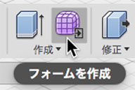
The Sculpting Process
Click the “Create Form” button on the Model Mode toolbar to enter Sculpt Mode.
(Demo) Create > Rectangular Prism
(Demo) Create > Cylinder
(Demo) Try out various edits.
Click the “Close Form” button to return to Model Mode.
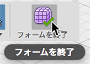
The final step is to switch back to Model mode to finish the model. In other words, T-Splines is intended solely as an intermediate step in the modeling process. *Is there a workflow where you use T-Splines as-is?
When you return to Model Mode, the T-Spline surface (Sculpt Mode) is converted to a NURBS surface (Model Mode).
Verify that the cuboid is a solid. Demonstrate using joints, etc.
Make sure the cylinder remains a surface.
Toolbar
It turns purple. The work environment becomes completely different from Model Mode.
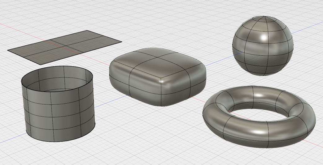
Primitive Shapes
Easy demos for everything
Display Mode
Extrusion
Rotation
Sweep
Loft
Edit Form
How to Select Faces, Edges, and Points
Inserting an Edge
Insertion Point
Joining Edges
Bridge
Not just the edges, but the surfaces as well
What is the difference between “Join Edges” and “Bridge”? How do you use them?
** **
Summary of the Features of Sculpture Modeling
It is more prone to errors than model mode (solid model). → A high level of quality is required for the CG data.
Edge spacing and curve gradient
Range of Influence
Self-intersection error (Seminar Materials: Basic Operations of the Sculpting Function, Session 4)
Correction > Standardization
Tips for Sculpt Modeling (Seminar Materials: Part 3—Is Fusion 360 Useful for Product Designers in Solving Problems?)
That concludes the basics of the sculpting feature; let’s move on to the practice exercises.